


35
Connecting Your Components—Continued
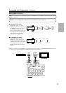
As of this printing, the Onkyo Remote Interactive Dock is the only HDD-compatible component available.
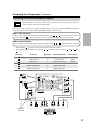
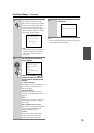
■ For HDD-compatible components that
support video
Connect your HDD-compatible component’s analog
audio output jacks and video output jack to the AV
receiver’s VIDEO 3 IN L/R jacks and VIDEO 3 IN
(V or S) jack.
(The hookup example below shows how to connect
the DS-A1.)
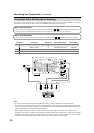
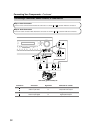
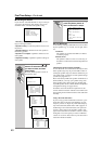
■ For HDD-compatible components that don’t
support video
Connect your HDD-compatible component’s analog
audio output jacks to the AV receiver’s TAPE IN L/R
jacks.
(The hookup example below shows how to connect
the DS-A1.)
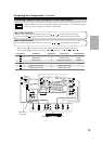
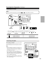
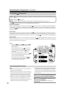
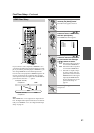
The AV receiver has AC outlets on its rear panel that can be
used to connect the power cords of other components that you
intend to use with the AV receiver. These components can
then be left turned on so that they turn on and off as and when
the AV receiver is turned on and set to Standby.
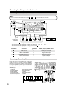
Caution:
• Make sure that the total capacity of the components that
you connect to the AC OUTLETS does not exceed the
stated capacity (e.g., TOTAL 120 W).
Note:
• Integra/Onkyo components connected via should be
connected directly to a wall outlet, not an AC OUTLET on
the AV receiver.
• The number of AC OUTLETS, socket type, and total
capacity depends on the country in which you purchased
the AV receiver.
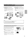
Connecting an HDD-compatible Component
S
VIDEO 3
IN
L
R
IN
VIDEO 3
L
R
IN
TAPE
Connecting the Power Cords of Other Components
Notes:
• Connect the Remote Interactive Dock with an cable (see page 36).
• Set the Remote Interactive Dock’s RI MODE switch to HDD.
• Set the AV receiver’s Input Display to HDD (see page 44).
• Refer to the Remote Interactive Dock’s instruction manual.
AC OUTLETS
AC
120
V 60
Hz
SWITCHED
TOTAL 120W 1A MAX.