


9
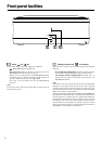
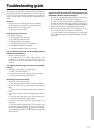
Rear panel facilities and connections
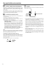
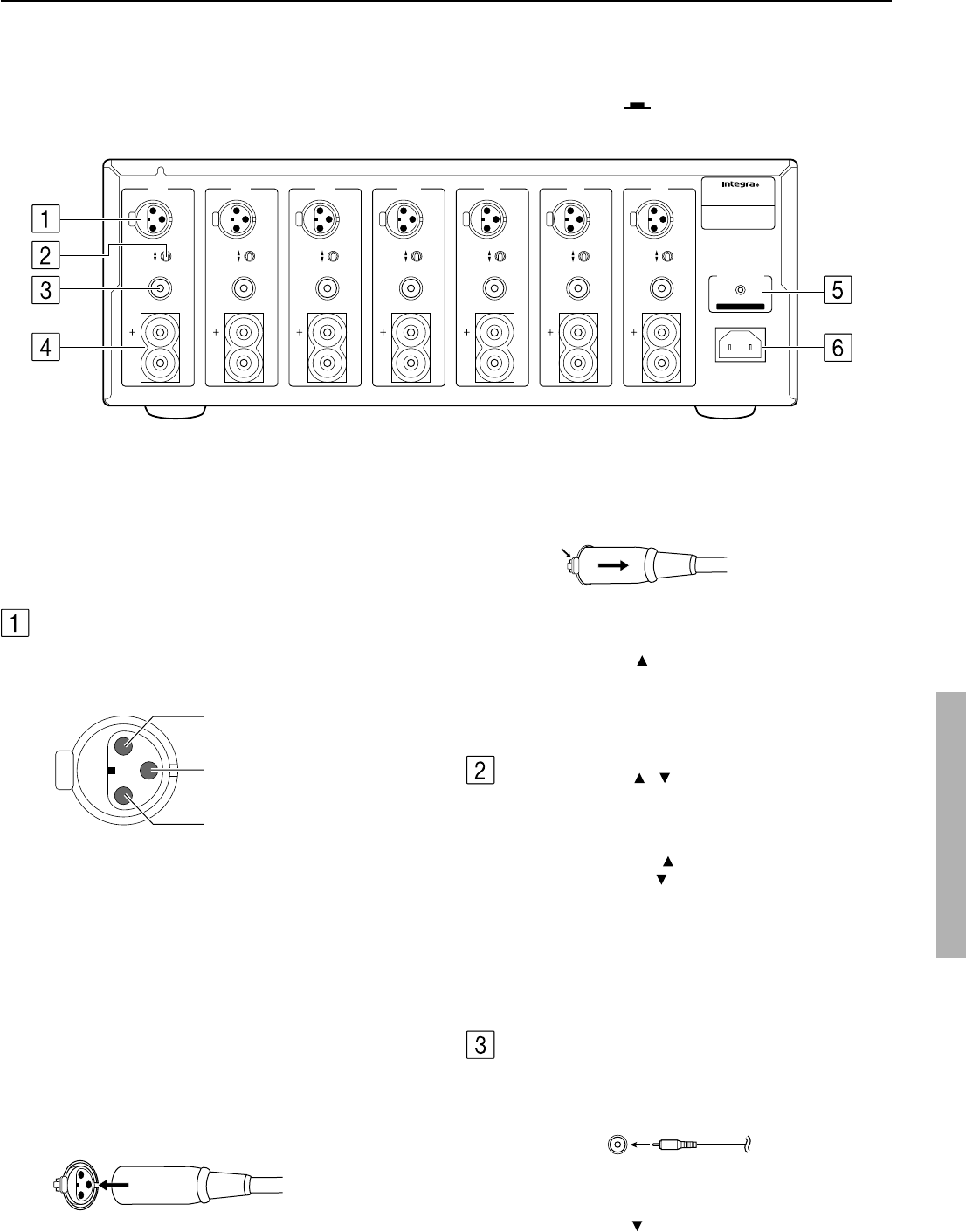
2. Disconnecting the input terminal
Pull out the connection cable while holding down the lever.
Note:
• When using this balanced connection for a specific channel
between the control amplifier and DTA-9.4, set the INPUT
SELECT switch to the
side (the balanced input side) to select
balanced input. Next, use commercial XLR balanced cable and
connect the balanced output from the control amplifier to the
corresponding balanced input on the DTA-9.4.
• Do not connect anything to the RCA-type audio input jack.
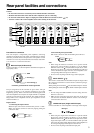
INPUT SELECT /
This switch is located between the balanced input and single-ended
RCA input for each channel. Use this switch to select the input type
for its channel.
When pushing the switch to the
side, the balanced input is selected.
When pushing the switch to the
side, the RCA audio input is selected.
Note:
• Do not change the INPUT SELECT switch setting when the
DTA-9.4 is turned on.
• Make sure that connections have been made only to the inputs
selected with the INPUT SELECT switches and nothing is
connected to the other ones.
Unbalanced Input (single end RCA input)
Connect controllers or control amplifiers with single-ended outputs.
Note:
• When using this single-ended connection for a specific channel
between the control amplifier and DTA-9.4, set the INPUT
SELECT switch to the
side (the RCA audio input side) to select
single-ended input. Next, use commercial RCA audio pin cable
and connect the single-ended output from the control amplifier to
the corresponding single-ended input on the DTA-9.4.
• Do not connect anything to the balanced input jack.
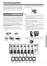
Precaution for connection
This unit comprises 7 independent power amplifiers, each being
capable of reproducing the same quality sound through its channel.
Note that you should connect an input source and a speaker to each
channel in use. Leave any unused channels unconnected, if the DTA-
9.4 is used for 2- or 5-channel connection.
Balanced Input (XLR terminal)
Connect controllers or control amplifiers with balanced outputs for
high-quality sound.
The pin assignments for this terminal are given above. This pin
assignment conforms to the standard adopted by the Audio
Engineering Society. Refer to the instruction manual supplied with
the control amplifier and verify that its output terminal is compatible
with the pin assignments for this terminal. The output terminal of
Integra DTC-9.4 is compatible with the pin assignments for the
terminal of DTA-9.4.
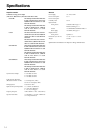
Input terminal
1. Connecting the input terminal
Match the pins and insert the terminal until you hear a “click.”
Make sure that the terminal is locked by lightly pulling the
connection cable.
Connector ground terminal: Chassis grounded
RCA type
1. GND
3. inverting (–)
2. non-inverting (+)
INPUT
SELECT
OUTPUT
INPUT
SELECT
OUTPUT
INPUT
SELECT
OUTPUT
INPUT
SELECT
OUTPUT
INPUT
SELECT
OUTPUT
INPUT
SELECT
OUTPUT
INPUT
SELECT
OUTPUT
AC
INLET
12
V TRIGGER IN
CONTROL
LINK
IN
MODEL NO.
DTA
-
9.4
SEVEN CHANNEL AMPLIFIER
SURROUND
RIGHT
RIGHT
SURROUND BACK
RIGHT
CENTER
SURROUND BACK
LEFT
SURROUND
LEFT
LEFT
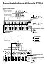
Caution
• Do not connect the Power cord until you have finished all other connections.
• Read the instructions that came with the other components you are connecting.
• Do not make connections to input or output jacks while the DTA-9.4 is turned on (Power
on).
• Turn the volume of the control amplifier down before turning on the DTA-9.4.
Push
12
3