


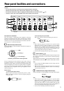


13
Troubleshooting guide
If the DTA-9.4 fails to function normally, first check the following
points before contacting your Integra/Onkyo dealer. If the problem
is not solved after going through the following list, unplug the
power cord and contact your Integra/Onkyo authorized service
center.
No power.
• Power cord is not correctly plugged into AC outlet/Inlet.
➞ Plug the power cord into the AC outlet/Inlet properly.
• Power switch is not set to ON position.
➞ Set the power switch to ON.
Power turns on but no sound.
• Incomplete connections.
➞ Check speaker cable connections.
➞ Insert all plugs firmly into jacks.
• No input signal from control amplifier.
➞ Check for input signal from control amplifier.
• Incorrect INPUT SELECT switch setting.
➞ Set INPUT SELECT switch to correct setting.
The On indicator lights blue and the Standby indicator
flashes red simultaneously.
• Protective circuitry activated.
➞ A problem such as a speaker cable shorting or the
temperature of the DTA-9.4 rising excessively may have
occurred. Turn power off immediately, locate problem, and
correct it.
The Standby indicator lights red and the On indicator
turns off.
• The DTA-9.4 waits for the 12V trigger signal.
➞ Turn on the control amplifier.
• Connection between the 12V trigger terminals is incomplete.
➞ Connect the cables to the terminals firmly.
Humming or other noise is heard.
• Input cable connection is incomplete.
➞ Insert the input cable to pin jack or connector completely.
• Noise from power cord or power transformer affects the input
cable.
➞ Keep power cord or power transformer away from the input
cable.
• Power cord or speaker cables are bundled together with pin
cords.
➞ This may cause humming or noise. Do not bundle power
cord or speaker cables with pin cables together.
• Connection to the input terminals is not complete or not
appropriate.
➞ For each channel’s input terminals, connect cables or cords
to either balanced input terminal or audio input terminal only
and switch the INPUT SELECT
/ switch accordingly.
Avoid connecting the cables or cords to the input terminals that
will not be used.
The dimmer function of the DTA-9.4 does not react to the
dimmer function of the DTC-9.4. (The brightness of the
On/Standby indicator cannot be changed.)
• The cable for the CONTROL LINK connection is connected to
the 12V TRIGGER OUT A terminal on the DTC-9.4.
➞ When the cable is connected to the 12V TRIGGER OUT A
terminal, the function link between the DTC-9.4 and DTA-9.4
does not work. Use the 12V TRIGGER OUT B (CONTROL
LINK OUT) terminal for the CONTROL LINK connection.
• The stereo mini-plug cable other than the supplied one is used
for the connection between the DTC-9.4 and DTA-9.4.
➞ Use the supplied stereo mini-plug cable. Any other cables
does not allow the function link between the DTC-9.4 and DTA-
9.4 to work.