


12
R
L
R
L
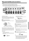
PRE OUT
FRONT
SUB
SURR
SURR
BACK/
ZONE 2
CENTER
INPUT
SELECT
OUTPUT
INPUT
SELECT
OUTPUT
INPUT
SELECT
OUTPUT
INPUT
SELECT
OUTPUT
INPUT
SELECT
OUTPUT
INPUT
SELECT
OUTPUT
INPUT
SELECT
OUTPUT
AC
INLET
12
V TRIGGER IN
CONTROL
LINK
IN
MODEL NO.
DTA
-
9.4
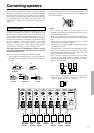
SEVEN CHANNEL AMPLIFIER
SURROUND
RIGHT
RIGHT
SURROUND BACK
RIGHT
CENTER
SURROUND BACK
LEFT
SURROUND
LEFT
LEFT
LEFTRIGHTCENTERSUBWOOFER
SURROUND
LEFT
SURROUND
RIGHT
SURR BACK
/
ZONE 2
LEFT
SURR BACK
/
ZONE 2
RIGHT
PRE OUT
INPUT
SELECT
OUTPUT
INPUT
SELECT
OUTPUT
INPUT
SELECT
OUTPUT
INPUT
SELECT
OUTPUT
INPUT
SELECT
OUTPUT
INPUT
SELECT
OUTPUT
INPUT
SELECT
OUTPUT
AC
INLET
12
V TRIGGER IN
CONTROL
LINK
IN
MODEL NO.
DTA
-
9.4
SEVEN CHANNEL AMPLIFIER
SURROUND
RIGHT
RIGHT
SURROUND BACK
RIGHT
CENTER
SURROUND BACK
LEFT
SURROUND
LEFT
LEFT
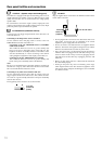
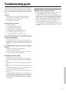
Note:
• When using the balanced
inputs, do not connect
anything to the RCA inputs.
• Make sure that the
balanced cable is not split.
The split balanced cable
may be the cause of noise.
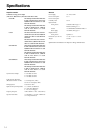
Note:
• When using the RCA inputs, do not connect anything to the
balanced inputs.
• Make sure that the pin cable is not split. The split pin cable may
be the cause of noise.
Improper connection
Inserted completely
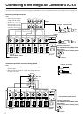
Connecting to the Integra AV Controller DTC-9.4
Since many users will purchase the DTA-9.4 together with the DTC-9.4, here is an explanation of how to connect the DTA-9.4 to the DTC-9.4.
Balanced input/output connection
DTC-9.4
DTA-9.4
At the DTC-9.4
XLR type
At the DTA-9.4
Push the INPUT SELECT
switch upward
Connect to the DTC-9.4
12V TRIGGER OUT B (CONTROL LINK
OUT) terminal
(using supplied stereo mini-plug cable)
Unbalanced input/output connection RCA type cable
Push the INPUT SELECT switch
downward
Connect to the DTC-9.4
12V TRIGGER OUT B (CONTROL LINK
OUT) terminal
(using supplied stereo mini-plug cable)
DTA-9.4
DTC-9.4
Balanced cable
DTC-9.4
DTC-9.4