


ii
TABLE OF CONTENTS
INSTALLATION NOTES
The installation of this equipment should be
made in such a manner as to respect the EC
recommended electromagnetic field expo-
sure limits (1999/519/EC).
The maximum RF power available from this
device is 25 watts. The antenna should be
installed as high as possible for maximum ef-
ficiency and that this installation height
should be at least 5 meters above ground (or
accessible) level. In the case where an an-
tenna cannot be installed at a reasonable
height, then the transmitter should neither be
continuously operated for long periods if any
person is within 5 meters of the antenna, nor
operated at all if any person is touching the
antenna.
In all cases any possible risk depends on the
transmitter being activated for long periods.
(actual recommendation limits are specified
as an average of 6 minutes) Normally the
transmitter is not active for long periods of
time. Some radio licenses will require that a
timer circuit automatically cuts the transmit-
ter after 1–2 minutes etc.
Similarly some types of transmitter, SSB,
CW, AM, etc. have a lower ‘average’ output
power and the perceived risk is even lower.
1 OPERATING RULES .......................... 1
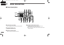
2 PANEL DESCRIPTION .................. 2–5
■ Panel description ............................. 2
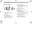
■ Function display ............................... 4
■ Microphone ...................................... 5
3 BASIC OPERATION .................... 6–10
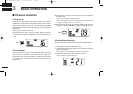
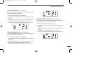
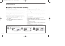
■ Channel selection ............................ 6
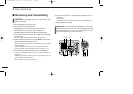
■ Receiving and transmitting .............. 8
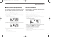
■ Call channel programming ............... 9
■ Channel names ................................ 9
■
Optional voice scrambler operation
.. 10
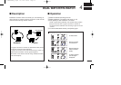
4 DUALWATCH/TRI-WATCH ............... 11
■ Description ..................................... 11
■ Operation ....................................... 11
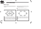
5 SCAN OPERATIONS ................. 12–13
■ Scan types ..................................... 12
■ Setting tag channels ...................... 13
■ Starting a scan ............................... 13
6 SET MODE ................................. 14–16
■ Set mode programming ................. 14
■ Set mode items .............................. 15
7 CONNECTIONS AND
MAINTENANCE ......................... 17–22
■ Unpacking ...................................... 17
■ Antenna ......................................... 17
■ Fuse replacement .......................... 17
■ Cleaning ......................................... 17
■ Connections ................................... 18
■ Mounting the transceiver ............... 19
■ Optional unit installation ................. 21
■ Dimensions..................................... 20
8 TROUBLESHOOTING ...................... 23
9 CHANNEL LIST ................................ 24
10 SPECIFICATIONS AND OPTIONS ... 25
■ Specifications ................................. 25
■ Options .......................................... 25
MB-75 TEMPLATE
0 IC-M501EURO_3.qxd 03.7.29 15:26 Page c