


Getting Started
Getting Started
F
EN
ES
C
3
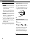
Identifying Parts and Controls
See the pages in parentheses for further details.
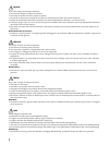
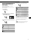
Front
1 ? (reset) button (page 15)
Resets the adjustments to the factory settings.
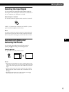
2 (auto sizing and centering) button
(page 5)
This button automatically adjusts the size and centering
of the picture.
3 Input 1-2 switch (pages 5)
This switch selects the INPUT 1 (Video input 1
connector) or INPUT 2 (Video input 2 connector).
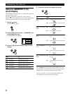
4 ¨ (brightness) down and up (./>) buttons
(pages 6 – 15)
Adjust the picture brightness.
Function as the (./>) buttons when adjusting other
items.
5 (menu) button (pages 6 – 15, 17)
Displays the MENU OSD.
6 > (contrast) left and right (?//) buttons
(pages 6 – 15, 20)
Adjust the contrast.
Function as the (?//) buttons when adjusting other
items.
7 u (power) switch and indicator (pages 16,
20)
Turns the monitor on or off.
The power indicator lights up in green when the
monitor is turned on, and either flashes in green and
orange, or lights up in orange when the monitor is in
power saving mode.
12
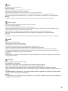
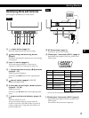
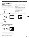
Rear
8 AC IN connector (page 4)
Provides AC power to the monitor.
9 Video input 1 connector (HD15) (page 4)
Inputs RGB video signals (0.700 Vp-p, positive) and
SYNC signals.
Getting Started
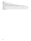
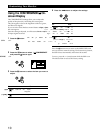
Pin No.
1
2
3
4
5
6
7
Pin No.
8
9
10
11
12
13
14
15
Signal
Red
Green
(Sync on Green)
Blue
ID (Ground)
DDC Ground*
Red Ground
Green Ground
Signal
Blue Ground
—
Ground
ID (Ground)
Bi-Directional
Data (SDA)*
H. Sync
V. Sync
Data Clock(SCL)*
* Display Data Channel (DDC) Standard of VESA
1 2 3 4
5
876
11 12 13 14 15
10
9
!ºVideo input 2 connector (HD15) (page 4)
Inputs RGB video signals (0.700 Vp-p, positive) and
SYNC signals.
See the above table for the pin assignment.