


34-ST-03-57
Page 8
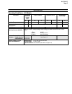
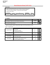
Performance Under Rated Conditions * - Models STR94G (0 to 500 psi/35 bar)
Parameter Description
Upper Range Limit psi
bar
500
35
Minimum Span psi
bar
20
1.4
Turndown Ratio
25 to 1
Zero Elevation and Suppression
No limit except minimum span from absolute 0 (zero) to +100% URL.
Accuracy (Reference – Includes
combined effects of linearity,
hysteresis, and repeatability)
•
Accuracy includes residual error
after averaging successive
readings.
• For FOUNDATION Fieldbus use
Digital Mode specifications. For
HART use Analog Mode
specifications.
In Analog Mode: ±0.10% of calibrated span or upper range value (URV), whichever is
greater, terminal based.
In Digital Mode: ±0.075% of calibrated span or upper range value (URV), whichever
is greater, terminal based.
* Performance specifications are based on reference conditions of 25°C (77°F), zero (0) static pressure, 10 to 55% RH, and
316L Stainless Steel barrier diaphragm.
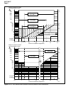
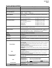
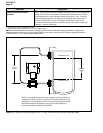
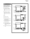
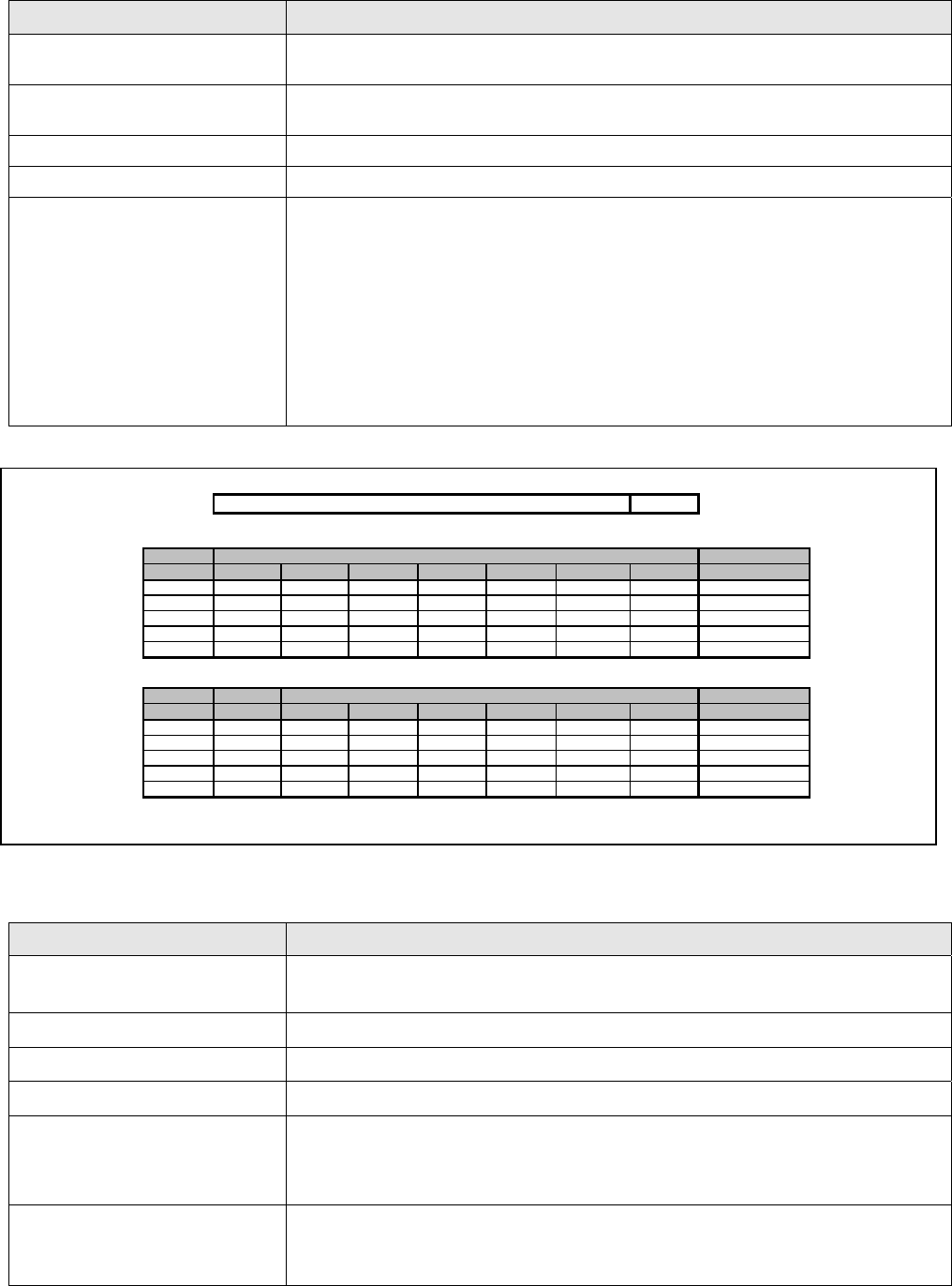
Transmitter Minimum Span and Maximum Capillary Length
Minimum recommended span for STR93D DP Transmitter with two Remote Seals
Diaphragm Capillary Length
Size 5' 10' 15' 20' 25' 30' 35' maximum
2.0
15 psig 20 psig 25 psig - - - - 15'
2.4
150 iwc 200 iwc 250 iwc 300 iwc 350 iwc 400 iwc 450 iwc 35'
2.9
50 iwc 75 iwc 100 iwc 125 iwc 150 iwc 175 iwc 200 iwc 35'
3.5
25 iwc 25 iwc 25 iwc 28 iwc 32 iwc 36 iwc 40 iwc 35'
4.1
25 iwc 25 iwc 25 iwc 25 iwc 25 iwc 27 iwc 30 iwc 35'
Minimum recommended span for STR94G or STR93D DP Transmitter with one Remote Seal
Diaphragm Direct Capillary Length
Size Mount 5' 10' 15' 20' 30' 35' maximum
2.0
25 psi 30 psi 40 psi 50 psi - - - 15'
2.4
10 psi 15 psi 20 psi 25 psi 30 psi 40 psi 50 psi 35'
2.9
8 psi 9 psi 10 psi 11 psi 12 psi 14 psi 15 psi 35'
3.5
2 psi 2 psi 3 psi 4 psi 5 psi 7 psi 8 psi 35'
4.1
0.9 psi 0.9 psi 1 psi 2 psi 3 psi 4 psi 5 psi 35'
Minimum span is the higher of the value from the table above or the value defined under Performance Conditions for the range transmitter
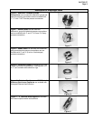
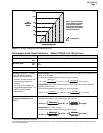
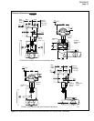
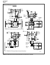
Capillary
Capillary
Figure 15— Maximum capillary length and diaphragm size chart.
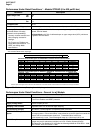
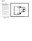
Performance Under Rated Conditions - General for all Models
Parameter Description
Output (two-wire) Analog 4 to 20 mA or DE digital communications mode. Options available for
F
OUNDATION Fieldbus and HART protocols.
Supply Voltage Effect 0.005% of span per volt.
Damping Time Constant Adjustable from 0 to 32 seconds digital damping.
CE Conformity (Europe) 89/336/EEC, Electromagnetic Compatibility (EMC) Directive.
NAMUR NE 43 Compliance
Option
Transmitter failure information is generated when the measuring information is invalid or
no longer present. Failure information is transmitted as a current signal but outside the
normal 4-20 mA measurement signal level. Transmitter failure values are:
≤ 3.6 mA and ≥ 21.0 mA. The normal signal range is ≥ 3.8 mA and ≤ 20.5 mA.
SIL 2/3 Compliance
SIL certified to IEC 61508 for non-redundant use in SIL 2 related Safety Systems
(single use) and for redundant (multiple) use in SIL 3 Safety Systems through
TÜV Nord Sys Tec GmbH & Co. KG under the following standards: IEC61508-1: 1998;
IEC 61508-2: 2000; IEC61508-3: 1998.