


34-ST-03-57
Page 7
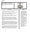
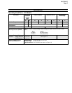
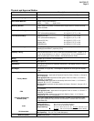
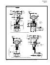
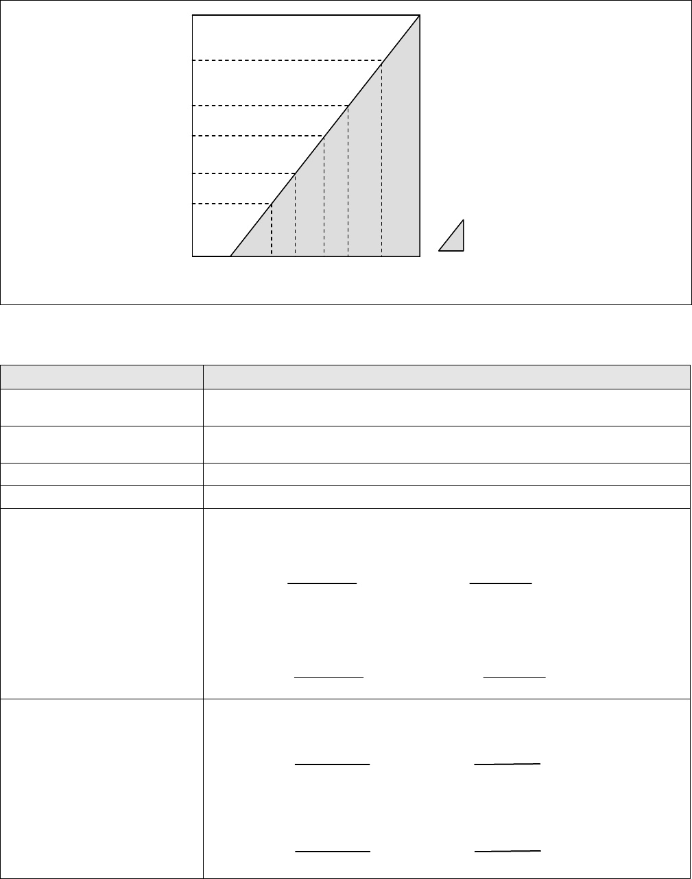
Note: A minimum of 250 ohms
of loop resistance is necessary
to support communications.
Loop resistance equals barrier
resistance plus wire resistance
plus receiver resistance.
= Operating Area
0 10.8 16.28 20.63 25 28.3 37.0 42.4
1440
1200
800
650
450
250
Operating Voltage (Vdc)
Loop
Resistance
(ohms)
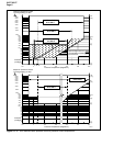
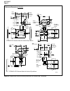
Figure 14—Supply voltage and loop resistance chart
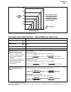
Performance Under Rated Conditions * - Model STR93D (0 to 100 psi/7 bar)
Parameter Description
Upper Range Limit psi
bar
100 (Transmitter URL or maximum seal pressure rating, whichever is lower.)
7
Minimum Span psi
bar
0.9
0.063
Turndown Ratio
110 to 1
Zero Elevation and Suppression
No limit except minimum span within ±100% URL.
Accuracy (Reference – Includes
combined effects of linearity,
hysteresis, and repeatability)
• Accuracy includes residual error
after averaging successive
readings.
• For F
OUNDATION Fieldbus use
Digital Mode specifications. For
HART use Analog Mode
specifications.
In Analog Mode: ±0.20% of calibrated span or upper range value (URV), whichever is
greater, terminal based.
For URV below reference point (50 inH
2
O), accuracy equals:
±0.10 + 0.10
⎝
⎛
⎠
⎞
50 inH
2
O
span inH
2
O
or ±0.10 + 0.10
()
125 mbar
span mbar
in % of span
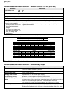
In Digital Mode: ±0.175% of calibrated span or upper range value (URV), whichever
is greater, terminal based.
For URV below reference point (50 inH
2
O), accuracy equals:
±0.075 + 0.10
⎝
⎛
⎠
⎞
50 inH
2
O
span inH
2
O
or ±0.075 + 0.10
()
125 mbar
span mbar
in % of span
Combined Zero and Span
Temperature Effect per 28°C
(50°F) **
In Analog Mode: ±1.5% of span.
For URV below reference point (200 inH
2
O), effect equals:
±0.30 + 1.2
200 in H
2
O
span in H
2
O
⎝
⎛
⎠
⎞
or ±0.30 + 1.2
500 mbar
span mbar
⎝
⎛
⎠
⎞
In % span
±0.30 + 1.2
200 in H
2
O
span in H
2
O
⎝
⎛
⎠
⎞
200 in H
2
O
span in H
2
O
⎝
⎛
⎝
⎛
⎠
⎞
⎠
⎞
or ±0.30 + 1.2
500 mbar
span mbar
⎝
⎛
⎠
⎞
500 mbar
span mbar
⎝
⎛
⎝
⎛
⎠
⎞
⎠
⎞
In % span
In Digital Mode: ±1.475% of span.
For URV below reference point (200 inH
2
O), effect equals:
±0.275 + 1.2
200 in H
2
O
span in H
2
O
⎝
⎛
⎠
⎞
or ±0.275 + 1.2
500 mbar
span mbar
⎝
⎛
⎠
⎞
In % span
±0.275 + 1.2
200 in H
2
O
span in H
2
O
⎝
⎛
⎠
⎞
200 in H
2
O
span in H
2
O
⎝
⎛
⎝
⎛
⎠
⎞
⎠
⎞
or ±0.275 + 1.2
500 mbar
span mbar
⎝
⎛
⎠
⎞
500 mbar
span mbar
⎝
⎛
⎝
⎛
⎠
⎞
⎠
⎞
In % span
* Performance specifications are based on reference conditions of 25°C (77°F), zero (0) static pressure, 10 to 55% RH, and
316L Stainless Steel barrier diaphragm.
** Specification applies to transmitters with 2 seals only. Apply 1.5 times factor to temperature effect for capillary lengths greater than 10 feet
or for 2-inch sanitary seals.