


TB 9-6625-2049-35
4
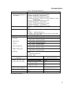
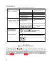
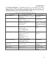
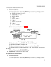
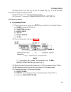
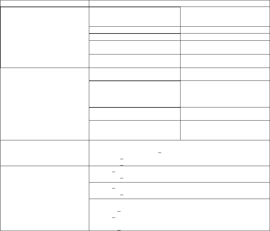
Table 1. Calibration Description - Continued
Test instrument parameters Performance specifications
Amplitude accuracy with dc
offset and no attenuation
(range 1) into 50Ω load
Tolerance relative to
programmed amplitude
Sine wave: .001 Hz to 100 kHz
±0.3 dB
Square: .001 Hz to 100 kHz
±3%
Triangle: .001 Hz to 2 kHz
2 kHz to 10 kHz
±4%
±6%
Ramps: .001 Hz to 500 Hz
500 Hz to 10 kHz
±4%
±11%
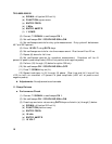
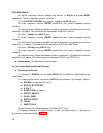
Function and frequency range
Tolerance relative to
programmed amplitude
Attenuator accuracy (these
errors are additive with the
amplitude accuracy errors)
.001 Hz to 100 kHz
Attenuator ranges 2 through 8
±0.1 dB
100 kHz to 10 MHz
Attenuator ranges 2 through 8
±0.2 dB
10 MHz to 20 MHz
Attenuator ranges 2 through 4
Attenuator ranges 5 through 8
0.2 dB
±0.5 dB
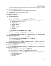
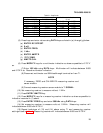
Amplitude output Range: 1.000 mV to 10.00 V p-p
Amplitude (option 002)
(high voltage output)
Range: 4 mV to 40 V p-p (>500Ω)
Accuracy: +2% of full output for each range at 2 kHz
Flatness: +10% of programmed amplitude
Dc offset Range: +5 V dc
Accuracy: +0.4% of full peak output for each attenuator range
2
Dc offset (option 002) Range: +20 V dc
Accuracy: + (1% +25 mV) of full output for each attenuator range
Dc plus ac Range: <1 MHz
Accuracy: +1.2%
Ramps: +2.4%
Range: >1 MHz
Accuracy: +3%
1
Not verified below 50 Hz.
2
Except lowest attenuator range where accuracy is ±20 µV.
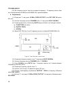
SECTION II
EQUIPMENT REQUIREMENTS
4. Equipment Required. Table 2. identifies the specific equipment to be used in this
calibration procedure. This equipment is issued with Secondary Transfer Calibration
Standards Set AN/GSM-287. Alternate items may be used by the calibrating activity. The
item selected must be verified to perform satisfactorily prior to use and must bear evidence
of current calibration. The equipment must meet or exceed the minimum use specifications
listed in table 2. The accuracies listed in table 2 provide a four-to-one ratio between the
standard and TI.