


TB 9-6625-2049-35
15
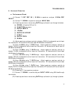
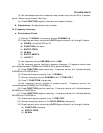
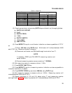
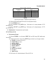
Table 3. Amplitude
Test instrument settings Multimeter indications
ENTRY AMPTD ENTRY FREQ
(V ac)
3.536 V RMS 1 kHz 3.495 3.577
3.536 V RMS 100 kHz 3.495 3.577
1.061 V RMS 100 kHz 1.048 1.073
1.061 V RMS 1 kHz 1.048 1.073
1.061 V RMS 100 Hz 1.048 1.073
.3536 V RMS
1
100 Hz 0.3416 0.3660
.3536 V RMS 1 kHz 0.3416 0.3660
.3536 V RMS 100 kHz 0.3416 0.3660
1
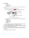
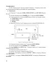
Press ENTRY DC OFFSET key and enter 1 mV using DATA keys.
(5) Press keys and enter values using DATA keys as listed in (a) through (g) below:
(a) ENTRY DC OFFSET.
(b) 0 mV.
(c) ENTRY FREQ.
(d) 1 kHz.
(e) ENTRY AMPTD.
(f) .707 V RMS.
(g) AMPTD CAL.
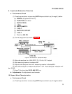
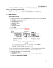
(6) Press MODIFY keys for a multimeter indication as close as possible to 0.707 V
ac.
(7) Enter 100 kHz using DATA keys. Multimeter will indicate between 0.683
and 0.732 V ac. Record multimeter indication.
(8) Disconnect multimeter and 50Ω feedthrough termination from TI.
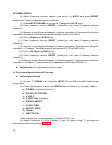
NOTE
If necessary, ZERO and CALIBRATE measuring receiver and
sensor module.
(9) Connect measuring receiver sensor module to TI SIGNAL.
(10) Set measuring receiver to measure volts at .1 MHz.
(11) Press ENTRY AMPTD key.
(12) Press MODIFY keys for a measuring receiver indication as close as possible to
indication recorded in (7) above.
(13) Press ENTRY FREQ key and enter 500 kHz using DATA keys.
(14) Set measuring receiver to measure volts at .5 MHz. Measuring receiver will
indicate between 0.683 and 0.732 V.
(15) Repeat technique of (13) and (14) above using TI and measuring receiver
settings listed in table 4. Measuring receiver will indicate between 0.683 and 0.732 V.