


TB 9-6625-2049-35
10
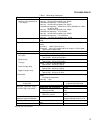
(a) SIGNAL off (option 002 not lit).
(b) FUNCTION square wave.
(c) ENTRY FREQ.
(d) 1 MHz.
(e) ENTRY AMPTD.
(f) 1 V RMS.
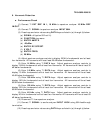
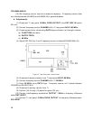
(2) Connect TI SIGNAL to oscilloscope CH 1.
(3) Set oscilloscope CH 1 COUPLING 50ΩΩ to ON.
(4) Set oscilloscope controls for duty cycle measurement. Duty cycle will be between
49.7 and 50.3 percent.
(5) Enter 10 VOLT using DATA keys.
(6) Set oscilloscope controls for rise time measurement. Rise time will be ≤20 ns.
(7) Repeat (6) above for fall time.
(8) Set oscilloscope controls for overshoot measurement. Overshoot will be ≤5
percent of peak to peak amplitude (≤500 mV at positive and negative peaks).
(9) Perform (10) through (12) below for option 002 only.
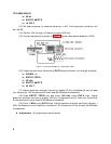
(10) Set oscilloscope CH 1 COUPLING 50ΩΩ to OFF.
(11) Press TI SIGNAL key on (lit).
(12)
Repeat technique in (6) through (8) above. Rise time and fall time will be
≤
125 ns with a
n overshoot <10 percent of peak amplitude (<500 mV at positive and
negative peaks).
b. Adjustments. No adjustments can be made.
11. Ramp Retrace
a. Performance Check
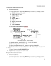
(1) Connect TI SIGNAL to oscilloscope CH 1.
(2) Set oscilloscope CH 1 COUPLING 50ΩΩ to ON.
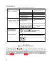
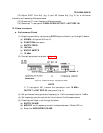
(3) Press keys and enter values using DATA keys as listed in (a) through (f) below:
(a) SIGNAL off (option 002 not lit).
(b) FUNCTION positive ramp.
(c) ENTRY FREQ.
(d) 10 kHz.
(e) ENTRY AMPTD.
(f) 10 VOLT.