


3
your wire is to large to fit into the binding post use a short section of wire and a wire nut to
complete the connection. Weatherproof the wire nut connection. It is important to keep the
ground wire away from metal on the way to ground rod to get good range and provide the
best lightning protection. Keep the ground wire away from other metal if at all possible. (See
hints page) A couple inches away is fine. Cable the unit to the inside to provide power and
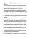
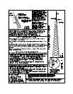
audio for the transmitter. See included diagram. The unit requires a 102” whip antenna that
can be purchased at Radio Shack, Stock # 21-903. It can be steel or fiberglass. The striped
wire is plus + on included wall power supply.
Begin the Tuning: You will need the following
Meter Tuning tool (supplied)
Small flathead screwdriver Medium Phillips screwdriver
The VOM or volt ohm meter can be bought at a Radio Shack if you don’t have one. Be sure
the crystal is installed if you are not using the agile module.
The crystal will not lock into the board, just seat it into the socket pins, it won’t fall out.
The following are instructions to tune with a meter, see Am1000T page to use the computer.
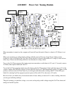
Check that “TUNE” is set 1/2 way between the counter- clockwise position (Min.
Capacitance) and clockwise position (Max. Capacitance). Use the tuning tool to tune. When
“TUNE” is turned fully either way be careful not to apply to much force. Permanent damage
may result. “TUNE” will turn about 10 turns. Make sure that the “Power Adjust” control is set to
about 1/2 of the way from counter clockwise. It is a 1 turn control. Set “AUDIO LEVEL” all the
way down (counter – clockwise). Important Note: (TURN IT BACK UP WHEN YOU ARE DONE
TUNING!) (This is a commonly missed item)
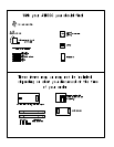
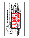
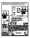
Set the “POWER SWITCH” to on. “Cabling note, you can use either terminal block for
cabling they are both the same, (+ and – is for power NOT S+ and S-, AF+ and AF- is audio)”
Check all of your cabling, turn the power on. You should be able to see the power light come
on. See cable diagram in this Manual for cabling examples. When using the control cable
Ferrite if the hole is to big try to loop the cable through twice. The ferrite installs on the audio
cable just outside the transmitter box.
Step 3
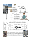
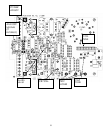
There are 3 test hole pads on the unit (see diagram). Take a standard voltmeter that is set to
DC 5-20 volts and plug it into the bottom and top test hole pads. The black lead will go to the
test hole pad closest to the mounting hole (Ground) (Top).
Next move the jumper on the “COIL TUNE” jumper block one at a time to find the one that
gives the highest meter reading or highest power amp voltage. Be sure that only one jumper
is used at a time. Leave this jumper on the highest meter reading and proceed. If you find 2
areas of the jumper block that give a peak reading one of them may be an harmonic. Chose
the position closest to the center of the jumper block range. If you are not seeing a good
meter reading then rotate the PWR control until you do, or check your meter.