


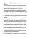
Now mount the transmitter to the mast using the bracket (see bracket instructions). If you are not using
a bracket, install transmitter to wall or acceptable configuration. Install 102” Antenna (Radio Shack #
21-903) to the transmitter, it screws into the top.
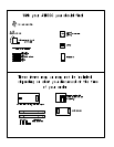
Connect the audio/power wire as shown on first page diagram, the ground wire connects to the post at
bottom of transmitter. Go ahead and connect power/audio and turn on. Be sure the power switch in the
transmitter is ON. If your unit is crystal - controlled be sure the crystal is installed (socket to the middle
right). If you are using the agile module, using the supplied chart, check your frequency.
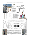
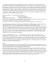
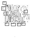
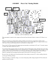
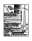
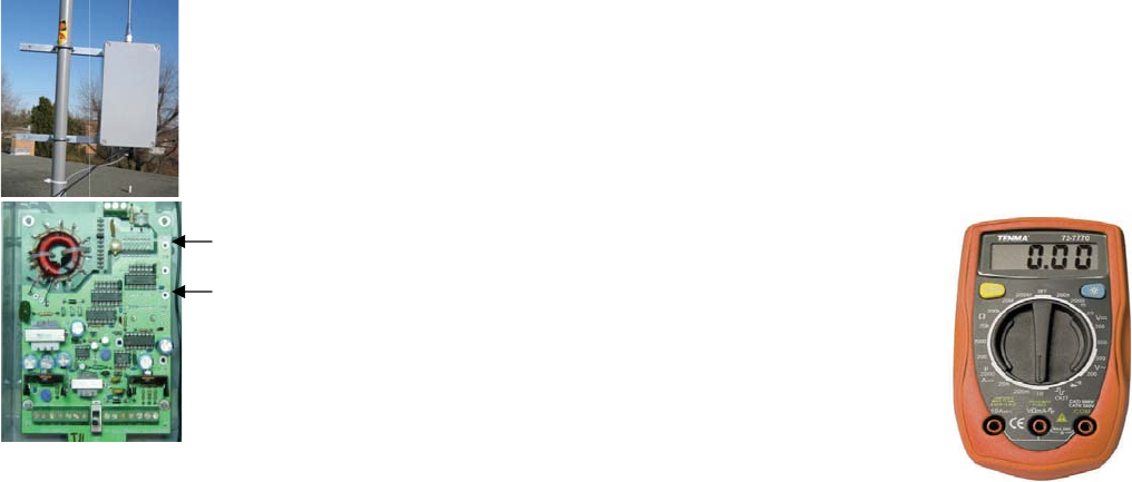
It is possible to tune using the computer circuit, see the manual. Using a meter
(available from RangeMaster) place the red lead in the bottom of the three test
holes, the black lead in the top test hole, the middle hole is unused . The power
control (bottom left of board) should be up about 1/3-1/2 turn. (The control near
the middle of the board is the audio gain, turn it all the way down now for tun-
ing). Set the meter to a low DC voltage, 10VDC, 20VDC is fine. This is the
meter setup to take the VOLTAGE.
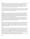
There is a 12 position header to the right of the large round red coil. Keeping
your hands away from the antenna and coil best you can move the shunt up and
down the header, try to find the position that gives the highest reading on the
meter. This position should be near the middle of the range of the header. If
there are two places where the voltage goes up, select the one near the middle.
Then using the provided tuning tool, turn the 10 turn device (capacitor) screw just to the right of the shunt, try to increase
the voltage further. The goal is to find a peak voltage. You should be able to see the voltage go up, then down, as you rotate
the tool. If not, if you go all the way to the end of the travel of the 10 turns, try another shunt position. You need to find the
peak voltage in this step or you are not tuned and will not get good range. This tuning needs to be done when the transmitter
is in it’s final position, and with the ground wire locked down. You can not tune the transmitter first on the ground, & then
install it. Find the peak voltage, & then leave it there. Now be sure to turn to audio level adjust pot back up.
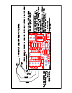
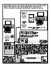
Setting the power is easy, with the AM1000T “green light” simply rotate the power control until the LED at the bottom of
the transmitter turns green. If you don’t have the AM1000T ,just refer to the “power chart” at the back of the manual for the
proper readings of VOLTAGE and CURRENT combinations possible. VOLTAGE is read the same way as when you were
tuning, to take the CURRENT reading just place the black lead in the bottom test hole and the red lead in the middle test
hole, read the voltage on the digital meter. Rotate the power control until the readings are in line with the chart.
It’s best to leave the audio adjust in the transmitter at 3/4 level, or all the way up, and adjust audio level from the ground.
There is also a gain adjust in the AM1000PR audio adapter module. Adjust the audio level for good sound on a test radio.
Your signal should sound as loud as other stations in the area. Get the audio level as high as you can without distortion. Try
not to have the test radio to close to the transmitter, it can get overloaded.
If you have trouble feel free to call, but check a few common problem first:
-Is your audio level high enough? Is it on? Audio is a gate on the power, if there isn’t enough audio the range will suffer
-Check the voltage at the terminal block with your meter, is there at least 12 volts there?
-Low range is often a bad ground, it could be poor soil conductivity in you area, a broken ground wire, or your ground rod
could be in sand or gravel instead of dirt. This is common when using an electrical meter rod, and/or if the rod is to close to
a building foundation. If you can just push your rod in the ground it is probably just sand, and it won’t work. Connections
can’t just be wrapped and taped, they need to be clamped. Clamps can be found at the hardware store. The copper needs to
be bright and shiny and the tightly clamped or soldered. Use an 8 foot rod if possible. Isolate the ground wire from metal on
the way down.
-Be sure you set the power properly
-Be sure the audio pot is turned up
-Be sure the crystal is in
-Here is a way to check transmitter operation: temporarily turn power up, you can draw a small spark from one of the round
red coil leads or the antenna with a lead pencil if the unit is working correctly. If it is to bright out you may not see the spark
RangeMaster Transmitters
(919)367-0607
Digital Volt Meter