


– 17 –
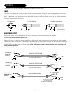
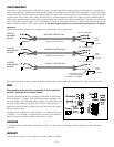
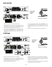
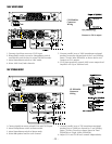
70V and 100V Mono mode also use the CH B input connector and level control only. The 70V or 100V speaker array load
should be connected across the red terminals of the output connectors. Set both load switches to the appropriate 70V or
100V value. The rated power into the mono load will be double the rating for a stereo load. See diagram
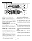
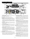
PROTECT
The red "Protect" LED on the front panel indicates that the NOMAD protection circuit has been activated, and is limiting
the output power of the amplifier. Typically this may only occur when a transient signal corresponds to a “dip” in the speak-
ers’ impedance curve, and will not cause significant clipping distortion. However, if the nominal speaker impedance is sig-
nificantly lower than the Load Switch setting, excessive clip distortion can result, accompanied by continuous or prolonged
illumination of the protect LED. In this situation the Load Switch should be changed to a lower value until the “protect”
events occur infrequently. See “Load Switch” paragraph.
LOAD SWITCH
The Load Switch-located on the front panel-allows the amplifier’s power supply to be matched to the speaker load for more
efficient, cooler running operation. The power output and thermal performance of the amplifier remains consistent with all
the possible combination of the loads listed. In Stereo or Biamp mode the Load switches can be configured independently,
and each channel will deliver the same consistent output power and thermal performance, regardless of how the other
channel is configured. Use the following guide when selecting the Load Switch setting:
Nominal Speaker Impedance Load Switch Setting
5Ω-8Ω or higher 8Ω
3Ω-5Ω 4Ω
2Ω-3Ω or lower 2Ω
If the “Protect” LED is illuminated for prolonged periods during normal operation, select the next lower value Load Switch
setting. Continue until the “Protect” LED ceases to illuminate, or lights infrequently. This switch can be safely operated
while the amplifier is running. In 70V or 100V mode, the “Protect” LED indicates there are too many speakers loading the
array.
THERMAL
Indicates when the thermal protection has shut down the amplifier. After cooling sufficiently, the amplifier will automatical-
ly recover and continue operating.
CLIPPING
Lights up when the output or input signal reaches the maximum allowable voltage, and “clips” the output signal. To deter-
mine whether the signal is clipping at the input or the output of the amplifier, perform this test: Turn the level control all the
way “OFF.“ If the clipping continues then the signal is clipping at the amplifier input. Input clipping occurs at 3Vrms (sine),
and can be eliminated by attenuating the signal before it reaches the amplifier. Output clipping can be eliminated by turn-
ing down the amplifier level control. Since this circuit triggers off the internal error signal of the amplifier, it automatically
adjusts for any combination of speaker impedance or Load Switch setting.
SIGNAL
Monitors the amplifier output and indicates when a signal of at least 1 Vrms is present. A number of situations could exist
where the input cable is properly connected to the signal source, but the Signal LED does not illuminate, such as:
Level control is not high enough to amplify the output signal to 1 Vrms.
Source signal is off, or lower than normal.
Input cable is not connected to CH B while in Biamp, Mono, 70V or 100V mode.
Biamp or Mono switch is not selected when using a single input cable.