


The Hafler GX2800 amplifiers are two rack height, two channel, fan-cooled professional power amplifiers suitable for use
in the most demanding sound reinforcement and commercial sound installations. These amplifiers offer outstanding effi-
ciency by means of three technologies: high-efficiency TRANS•
nova Class-G circuitry, high-frequency switching power
supplies, and constant power output/load impedance selection switches.
Introduction
Technical Design Features
WHY A NEW AMPLIFIER TOPOLOGY?
Hafler TRANS•nova amplifiers, the recording studio reference, have a floating +/- power supply for each channel and a
novel drive system covered by U.S. Patents 4,467,288 and 5,567,000. Our challenge was to convert this topology into a
high efficiency design with minimal increase in complexity-yielding an amplifier of outstanding audio qualities, high effi-
ciency and unprecedented value. TRANS•
nova Class-G is that answer.
The most common high-efficiency (Class-H) methods raise the rail voltages going to the output devices for higher power
levels. TRANS•
nova Class G does not do this. Instead, it operates by forming a triplet or triplex of tracking signals: A, (A+V)
and (A–V), where A is the raw audio output and +/– are the floating rails. The amplifier final output is selected to be at an
appropriate voltage between (A+V) and (A–V) for each condition of the signal. The output voltage and current capability are
each potentially doubled and the power potentially quadrupled–without having to increase the rail voltages fed to the
devices. One or more patents are expected from this technology.
WHAT ELSE DISTINGUISHES THESE AMPLIFIERS?
Constant power into varying impedances. It takes twice as much current to develop a given wattage into 2Ω as it does into
8Ω—but only half the voltage. Many amplifiers quote a high output current at 2Ω but have an unpublished operating time
measured in a handful of seconds—before thermal shutdown (hopefully) precludes thermal meltdown.
Our solution for this is
selectable rail voltages for optimizing the amplifier to the load. This is impractical for conventional
line-frequency supplies—and it comes at a cost for switching supplies. A full PWM design is needed, adding a coupled out-
put inductor, a current-sense transformer and a current-mode controller IC. An
impedance selector switch is also needed
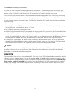
for each channel, simultaneously altering the rail voltage and the current limit. Each channel of the amplifier can be inde-
pendently optimized for 2Ω, 4Ω, and 8Ω, useful in bi-amping and tri-amping, etc. Both 70 and 100 volt constant voltage
line operation are possible. Instructions on the back of the amplifier explain the various options.
– 8 –