– 11 –
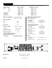
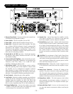
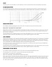
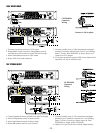
1. Recessed Front Panel - Prevents switches and controls from acci-
dentally being adjusted or broken.
2. Power Switch - Turns the amplifier ON and OFF
3. Power LEDs - Verifies that the amplifier channel is ON
4. Status LEDs - Displays the status of the amplifier. The LEDs are as
follows: SIGNAL indicates if signal is present; CLIP illuminates if
the amplifier is being overdriven; PROTECT illuminates if the
amplifier is experiencing a “short” in the speaker array; THER-
MAL illuminates if the amplifier has shut down due an overheat-
ing condition.
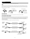
5. Female XLR & 1/4" TRS Input Jacks - Feeds input signal to the
amplifier using industry standard male XLR or 1/4" TRS
(tip/ring/sleeve) plugs.
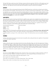
6. Crossover/Delay/CD Eq/Phase - Each channel has an inde-
pendendently configurable 500/800Hz, Low Pass/High Pass
Crossover; 0-30" Time Delay; 0 to +10dB CD Horn
Equalizer; 0/180 degree Phase switch.
7. Stereo/Mono Switch - This dual purpose switch is used to select
the operating mode of the amplifier. In Stereo mode the amplifi-
er can be configured for standard 2-channel stereo operation. In
Mono mode the amplifier can be configured for Standard Bridge
mono, 70V mono or 100V mono operation. Turn amplifier off
before operating this switch.
8. Level Controls - Adjusts the gain of the amplifier.
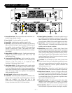
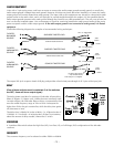
9. Load Switch - Selects the speaker impedance or transformer volt-
age that will be connected the output binding posts. In Standard
Mode the amplifier can drive 2Ω, 4Ω or 8Ω
speaker loads. In Constant Voltage Mode the amplifier can drive
an array of speakers using 70V or 100V transformers.
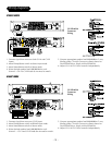
10. Output Speakon Connections - Connects the speaker array to
the amplifier. Individual Speakon connectors can be used for
stereo connections, or, a single 4-wire Speakon connector can
be used for stereo, BIAMP or mono mode speaker connections.
11. Internal Fans - internal fans keep the amplifier circuitry cool.
Allow a minimum of 3" clearance on the front and back of the
amplifier vents for adequate ventilation.
12. Chassis/Float ground switch - Isolates Audio Ground from
Chassis Ground (Chassis Ground is permanently connected to
Earth Ground through the third pin of the power cord). With the
switch in the "Chassis" position, the Audio Ground is connect-
ed to Chassis Ground. In the "Float" position, Audio Ground is
isolated ("floated") from Chassis Ground, and must be connect-
ed to Earth Ground by other means.
CAUTION: Do not attempt to "float" Audio Ground from
Chassis Ground unless you are absolutely certain there is some
other common ground between the amplifier and the source
equipment. Without this common ground, oscillations and
severe damage may occur.
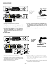
13. Mains Power Fuse - Protects the “mains” electrical circuit in
case abnormal current draw from the amplifier is experienced.
14. Mains Power Connector - Connects AC Voltage to the amplifi-
er. The power connector is safety approved IEC type 320. The
earth (safety) ground pin of the power connector is permanent-
ly connected to the chassis. This connection is capable of shunt-
ing in excess of 30A of fault current.
15. Biamp/Stereo Switch - This dual purpose switch selects either
standard 2-channel stereo mode or 1-channel in, 2 channels
out Biamp mode. Turn amplifier off before operating this switch.
16. Removable Rear Panel - 8 screws can be removed to service
fans and internal components without unracking the amplifier.