


– 18 –
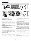
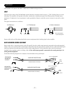
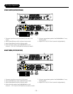
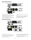
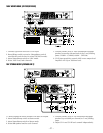
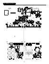
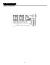
LOAD SWITCH
The Load Switch - located on the front panel - allows the amplifier power supply to be matched to the speaker load for
more efficient, cooler running operation.This unique feature of the GX2300/2600 allows each channel to be configured for
2Ω, 4Ω, 8Ω, or 70V, 100V mono operation. (also 70V Dual Mono-GX2600 only).
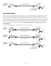
The power output and thermal performance of the amplifier remains consistent with all the possible combinations of the
loads listed. In Stereo or Biamp mode the Load switches can be configured independently, and each channel will deliver
the same consistent output power and thermal performance, regardless of how the other channel is configured. Use the fol-
lowing guide when selecting the Load Switch setting:
Nominal Speaker Impedance Load Switch Setting
5Ω-8Ω or higher 8Ω
3Ω-5Ω 4Ω
2Ω-3Ω or lower 2Ω
If the “Protect” LED is illuminated for prolonged periods during normal operation, select the next lower value Load Switch
setting. Continue until the “Protect” LED ceases to illuminate, or lights infrequently. This switch can be safely operated
while the amplifier is running. In 70V or 100V mode, the “Protect” LED indicates there are too many speakers loading the
array.
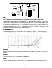
THERMAL
Indicates when the thermal protection has shut down the amplifier. After cooling sufficiently, the amplifier will automatical-
ly recover and continue operating.
CLIPPING
Lights up when the output or input signal reaches the maximum allowable voltage, and “clips” the output signal. Input clip-
ping occurs at 3 VRMs (sine), and can be eliminated by attenuating the signal at the source unit - before it reaches the
amplifier. Output clipping can be eliminated by turning down the amplifier level control.
To determine whether the signal is clipping at the input or output of the amplifier, perform this test: Turn the amplifier con-
trol all the way “OFF”. If the clipping continues, this is an indication that the signal is clipping at the amplifier input.
SIGNAL
Monitors the amplifier output and indicates when a signal of at least 1 Vrms is present. A number of situations could exist
where the input cable is properly connected to the signal source, but the Signal LED does not illuminate, such as:
Level control is not high enough to amplify the output signal to 1 Vrms.
Source signal is off, or lower than normal.