


– 10 –
WHAT ELSE DISTINGUISHES THESE AMPLIFIERS?
Constant power into varying impedance. It takes twice as much current to develop a given wattage into 2Ω as it does into
8Ω—but only half the voltage. Many amplifiers quote a high output current at 2Ω but have an unpublished operating time
measured in a handful of seconds—before thermal shutdown (hopefully) precludes thermal meltdown.
Our solution for this is selectable rail voltages for optimizing the amplifier to the load. This is impractical for conventional
line-frequency supplies—and it comes at a cost for switching supplies. A full PWM design is needed, adding a coupled out-
put inductor, a current-sense transformer and a current-mode controller IC. An impedance selector switch is also needed
for each channel, simultaneously altering the rail voltage and the current limit. Each channel of the amplifier can be inde-
pendently optimized for 2Ω, 4Ω, and 8Ω, useful in bi-amping and tri-amping, etc. Both 70 and 100 volt constant voltage
line operation are possible. A chart on the back of the amplifier explain the various options.
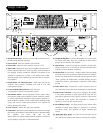
UNIVERSAL LINE VOLTAGE INPUT
Voltage selection is provided in two bands: 100-140 volts and 200-260 volts, (both 50/60 Hz) via two quick-connect termi-
nals located on the EMI filter board, accessed by removing the top cover. The current-mode control system automatically
corrects for the bulk of power line variation with each band. This allows most of the PWM action to be reserved for pro-
gramming and regulation of output voltages. A flyback topology provides the numerous housekeeping low voltages required
by various circuits.
PROTECTION CIRCUITS
Fan control circuit - Each amplifier channel has a fan control circuit that measures the temperature of the heatsink, and
adjusts the fan speed accordingly. This thermally-tracking fan speed circuit keeps fan noise to a minimum when power
demands are low. Typically the fans will be turning slowly even at idle conditions - although abnormally low room temper-
atures may allow the fans to turn off completely. The fan control circuit also has a turn-on blast feature that runs the fans at
full speed for a few seconds every time the amplifier is turned on. This serves the dual function of cleaning out the air tun-
nel, and providing a simple means to check the fans for proper operation. If you suspect that the fans are not operating cor-
rectly, try turning the amplifier off, then listening or feeling for the turn-on blast when the amplifier is turned back on.
Thermal Standby - If excessive heatsink temperature is detected, the individual amplifier channel will go into thermal stand-
by mode. The amplifier will be turned off, and the THERMAL LED illuminates until heatsink temperatures return to normal.
At that time the amplifier automatically turns back on, and continues operating normally.
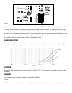
NOMAD protection - The amplifier output MOSFETs are protected from excessive power dissipation by NOMAD protec-
tion circuitry. NOMAD (Non-Multiplying Advance Decision) limits the power when it measures signal voltage and current
conditions that will exceed the pre-determined power limit of the MOSFETs. This instantaneous power calculation is per-
formed on each output MOSFET, causing the amplifier to automatically limit power when needed. In this way, a speaker
load with an impedance “dip” over a particular frequency range will only activate the NOMAD protection when sufficient
audio is present at that same frequency range, but continue operating normally otherwise.
Short protection - The NOMAD protection circuit also protects against shorts, and will instantly limit the output power if
speaker wires are shorted together. Normal operation will continue immediately after the short is removed.
Power Supply Current Limiting protection- The switching power supply will protect itself from excessive power dissipation
by continuously monitoring currents in the switching MOSFETs. The Current Limiting circuit measures the currents in the
switching MOSFETs and will instantly limit them to a safe level.
Soft turn-on/fast turn-off - Speaker loads are protected from turn-on/turn-off transients by a circuit that monitors the power
supply, and controls the amplifier when power on/off events are detected. At turn-on, this circuit waits for power supply
voltages to settle, then sends a turn-on ramp signal to slowly turn the amplifier on. At turn-off, this circuit acts quickly to
turn off the amplifier before power supply capacitors discharge, and voltages collapse into the output signal - causing
speaker “pops”.