


– 11 –
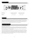
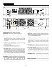
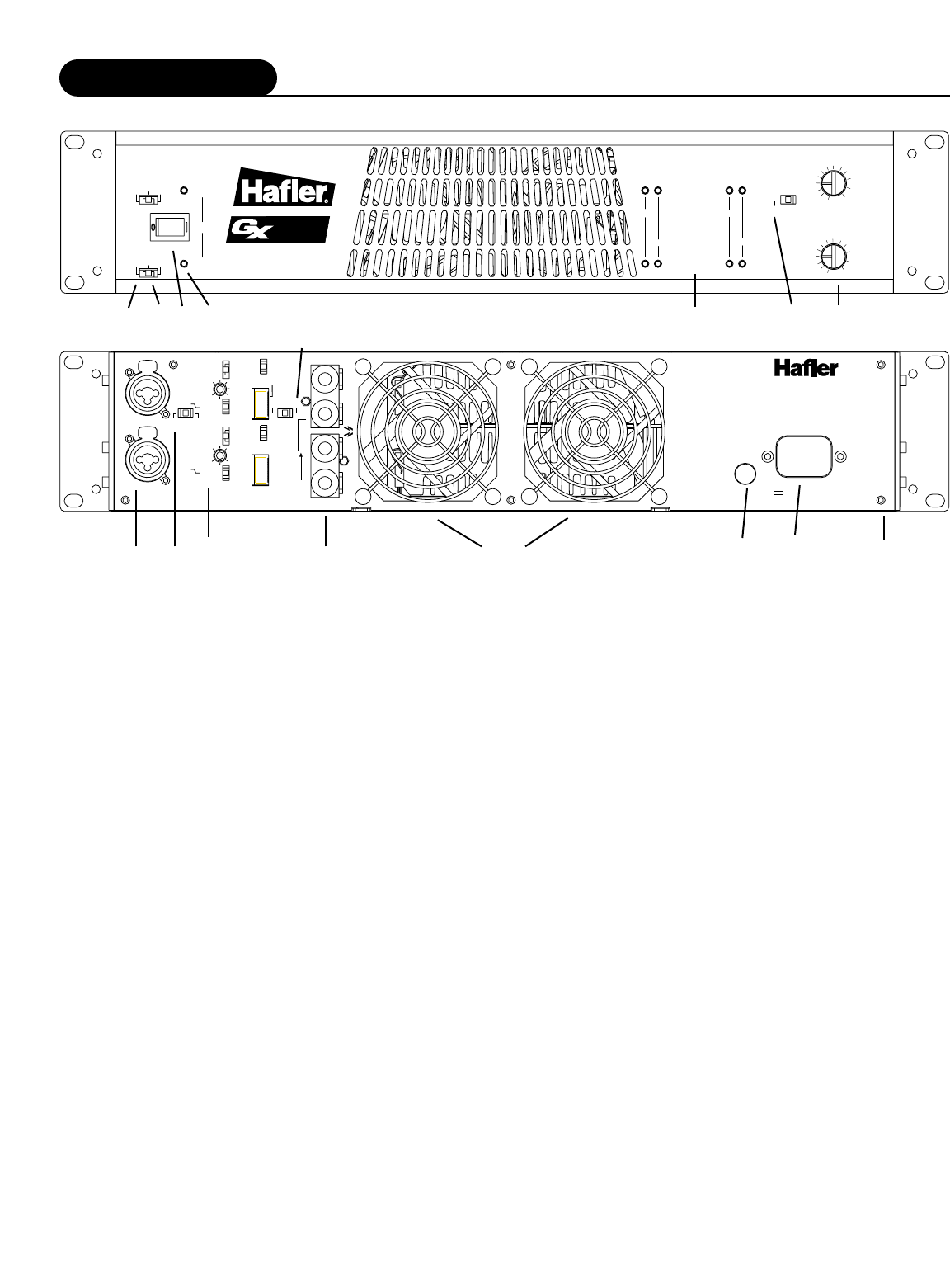
1. Recessed Front Panel - Prevents switches and controls from acci-
dentally being adjusted or broken.
2. Power Switch - Turns the amplifier ON and OFF
3. Power LEDs - Verifies that the amplifier channel is ON
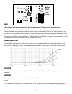
4. Status LEDs - Displays the status of the amplifier. The LEDs are as
follows: SIGNAL indicates if signal is present; CLIP illuminates if
the amplifier is being overdriven; PROTECT illuminates if the
amplifier is experiencing a “short” in the speaker array; THER-
MAL illuminates if the amplifier has shut down due an overheat-
ing condition.
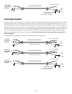
5. Female XLR & 1/4" TRS Input Jacks - Feeds input signal to the
amplifier using industry standard male XLR or 1/4" TRS
(tip/ring/sleeve) plugs.
6. Crossover/Delay/Phase/CD EQ - Each channel is
configurable for typical 2-way speaker systems.
7. Stereo/Mono Switch - This dual purpose switch is used to select
the operating mode of the amplifier. In Stereo mode the amplifi-
er can be configured for standard 2-channel stereo operation. In
Mono mode the amplifier can be configured for Standard Bridge
mono, 70V mono or 100V mono operation.
Turn amplifier off
before operating this switch.
8. Level Controls - Adjusts the gain of the amplifier.
9. Load Switch - Selects the speaker impedance or transformer voltage
that will be connected the output binding posts. In Standard Mode
the amplifier can drive 2Ω, 4Ω or 8Ω
speaker loads. In Constant Voltage Mode the amplifier can drive an
array of speakers using 70V or 100V transformers.
10. Output Binding Posts - Connects the speaker array to the ampli-
fier. These jacks allow bare wire, spade lugs or dual banana
plugs to be connected to the amplifier.
11. Internal Fans - internal fans keep the amplifier circuitry cool.
Allow a minimum of 3" clearance on the front and back of the
amplifier vents for adequate ventilation.
12. Chassis/Float ground switch - Isolates Audio GND and helps
eliminate noise in the signal chain. With the switch in “Chassis”
position, the Audio GND is connected to chassis ground. In the
“Float” position, the Audio GND is isolated (floating) from the
chassis.The chassis is permanently connected to earth (safety)
ground.
13. Mains Power Fuse - Protects the “mains” electrical circuit in
case abnormal current draw from the amplifier is experienced.
14. Mains Power Connector - Connects AC Voltage to the amplifi-
er. The power connector is safety approved IEC type 320. The
earth (safety) ground pin of the power connector is permanent-
ly connected to the chassis. This connection is capable of
shunting in excess of 30A of fault current.
15. Stereo/Biamp Switch - This dual purpose switch selects either
standard 2-channel stereo mode or 1-channel in, 2 channels
out Biamp mode.
Turn amplifier off before operating this
switch.
16.
16.
Removable Rear Panel
Removable Rear Panel - 8 screws can be removed to service
fans and internal components without unracking the amplifier.
Design Features
prot
ect
thermal
signal
clip
Stereo Mono
70V
100V
CH A
CH B
Power
Load
Channel A
70V
4Ω
2Ω
100v
8Ω
Channel b
-21
-18
-15
-12
-9
-6
-3
-24
-27
-32
-38
OFF
-21
-18
-15
-12
-9
-6
-3
-24
-27
-32
-38
OFF
0d
B
0d
B
2300
70V
4Ω
2Ω
100v
8Ω
®
Crossover
CD EQ
Freq
Freq
HP –
LP –
Full –
Delay
must
choose
one
only
500Hz –
800Hz –
180˚
–
0˚–
Phase
0”-
6”-
12”-
18”-
24”-
30”-
0”-
6”-
12”-
18”-
24”-
30”-
Crossover
CD EQ
500Hz –
800Hz –
180˚
–
0˚–
Phase
+10 dB
+0
+10 dB
+0
BIAMP STEREO
CH A
IN
—
+
300W
2Ω – 8Ω
Mono,70V,100V
Chassis
Float
Audio GND
CH B
IN
+
—
300W
2Ω – 8Ω
—
+
600W
(Mono)
4Ω– 16Ω
A Division of
Rockford Corp.
Tempe, AZ 85281
Made in the U.S.A.
300 W Stereo, 2Ω– 8Ω
600W Mono, 70V,100V
250W
115V~
50-60Hz
250V T7A
Attention: Utiliser un fusible
de rechange de même type.
CAUTION: For continued
protection from risk of fire,
replace only with same type
and rating of fuse.
HP
–
LP –
Full –
ON
ON
Class 2 wiring
For 70V, 100V, or Mono
• Use CH B input
• Load across RED terminals
• Set load switches to one
half load impedance
Delay
must
choose
one
only
2
6
2
6
GX2
3
00
1 9
2 3
4 7 8
5 15
6 10
11
14
16
12
13