– 13 –
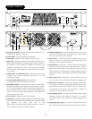
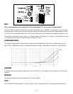
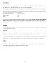
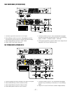
AUDIO GROUND CHASSIS/FLOAT SWITCH
In general, the Audio Ground of each amplifier should be connected to AC mains earth ground AT ONE POINT ONLY-
either through the Chassis (by selecting the "Chassis" position) OR through the input cable (with the switch in the "Float"
position, and pin 1 of the XLR or the sleeve of the
1/
4
" connected to the ground of the signal source unit.)
The Chassis/Float switch can be used as a means to troubleshoot ground loop problems, or to verify wiring. Ground loops
are characterized by a hum or buzz through the speakers, and occur when multiple paths exist for a given ground circuit.
This switch allows the Audio Ground to be temporarily "lifted" or "floated" from the chassis, so continuity tests can be made
to verify or reverse-engineer a grounding system. The following information will be useful when planning or troubleshoot-
ing system wiring:
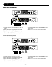
• The chassis is permanently connected to the earth (safety) ground pin of the Mains power connector.
• The Audio Ground of each GX2300/GX2600 is permanently connected to the black terminals of both output binding
posts, to pin 1 of each XLR input, and to the sleeve of each
1
/
4
" input.
• The XLR shell is permanently connected to chassis.
• With the Chassis/Float switch in the "Chassis" position, the Audio Ground will be connected to the Chassis and AC mains
earth ground. This connection is made through a 0Ω resistor (R350) located on the input board. The resistor serves as a
fuselink in the case of severe system faults. To check this resistor, remove all connectors from the amplifier and discon-
nect the AC main plug. With the switch in the "Chassis" position, use an ohmmeter to measure the 0Ω resistance between
the earth ground pin of the AC mains plug and Audio Ground at either black terminal of the output binding posts.
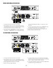
• By selecting the “Float” position, the Audio Ground is not directly connected to the chassis, and can be referenced to
some other ground through the input cable or speaker ground. For safety reasons, a 0.1µF capacitor (C125) permanently
connects Audio Ground and chassis. C125 is located on the input board. The 0.1µF capacitor couples Audio Ground to
chassis at RF frequencies, but only presents approximately 27kΩ of impedance at 60Hz.
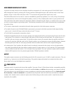
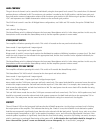
OUTPUT
The speaker output connectors are dual binding posts which will accept wire up to 12 AWG, or spade connectors. They are
spaced on
3
/
4
" centers for use with dual banana plugs. The positive output red terminals are oriented such that a dual
banana plug can be used for bridged mono operation.
POWER SWITCH
The power switch is located on the front of the amplifier. Two green "Power" LEDs indicate that the corresponding amplifier
channel is turned on. Standard practice is to turn the amplifier on last, and off first when powering your system on and off.
This insures that any turn on/off glitches in source components or signal processing equipment will occur before the ampli-
fier is turned on, or after it is turned off. It is possible to leave the power switch on at all times and switch the amplifier
remotely with a breaker switch or other AC power switch. When doing so make sure the switch is rated for the current
required by the amplifier.