


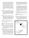
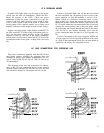

The DH-110 is provided with accessory Rack Mount end
caps in addition to the standard end caps installed on the
unit. These accessory caps extend the width of the front
panel to that of a standard 19” rack, with appropriate
mounting holes. Installation instructions are detailed later
in this manual under Additional Information.
POWER CONNECTIONS
As assembled, units are normally wired for 120 VAC,
50-60 Hz, as in the USA, unless they are specially iden-
tified on the carton. In the Additional Information section
you will find diagrams of alternate wiring of the power
transformer to conform to other line voltages.
The power regulation of the DH-110 will provide full per-
formance with line voltages which may vary substantially
from the standard. Units wired for 120 volts, for instance,
will work properly with line voltages between 95 and 130
volts.
Accessory AC outlets are provided on the back panel for
other equipment. One unswitched outlet is provided for a
turntable or tape recorder whose mechanical system may
require disengagement through its own power switch.
Most units, including power amplifiers, tuners, and many
tape recorders and record players, may be connected to
the switched outlets for convenient remote switching from
the preamp’s front panel. The DH-110 power switch has
been tested to provide adequate capacity for any Hafler
power amplifier and typical related equipment. You should
heed the maximum power rating printed on the back panel
of the unit.
INPUTS-Magnetic Phono
There are two pairs of phono inputs, identified as Phono
1
and Phono 2. These are independent, and thus they may
have different capacitive termination for differing car-
tridge requirements. As assembled, Phono 1 is provided
with a compensation capacitor of 120 picofarads, and
Phono 2 is provided with 220 picofarads. One of these val-
ues will accommodate most ‘Moving magnet’ cartridges.
These have output levels intended for normal phono in-
puts (0.5 millivolts per centimeter or higher) and are the
most popular. Some high output ‘moving coil’ design car-
tridges are not sensitive to capacitive loading, so they may
be used with either input.
Though some phono cartridges are comparatively free
of loading sensitivity, if the cartridge manufacturer
specifies the proper load capacitance (which is the sum of
the preamp’s internal capacitance, and the cables you use,
as well as the above described capacitor), the most accu-
rate sound will be obtained by following that recommenda-
tion. If you have chosen the DH-110 for its sonic attributes,
you will be more likely than most to be aware of these dif-
ferences, and will want proper cartridge termination.
The Additional Information section of this manual de-
tails the determination of the loading capacitor for a
specified cartridge load. It also describes how the resistive
load of the phono inputs may be changed, if needed, from
the standard 47K ohms.
Moving coil design cartridges often require an auxiliary
step-up transformer or pre-preamplifier (head amplifier)
because of their low output signal. The DH-110 has provi-
sion for internal addition of an accessory Hafler pre-
preamplifer which you or your dealer can install at any
time. This enables the Phono 1 input to accommodate such
cartridges directly. The Additional Information describes
its installation.
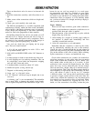
Adjacent to the Phono 1 input sockets are two Ground
terminals on the back panel. These thumbscrews provide
for connection of separate ground wires often provided on
turntables, or as part of their audio cables. This ‘chassis
ground’ may sometimes reduce the hum level of a system
when it is connected to an earth ground, such as a cold
water pipe, or the ground wire of 3-wire house wiring.
However, the need for such connection varies with indi-
vidual situations. After the system is operative, using a
phono source, experiment with and without an earth
ground to determine which provides the lowest hum, and
use that.
IMPUTS-Tuner, CD/Video
These are high level (line-50 millivolts or more) signals
from FM, AM or TV tuners, or compact digital audio disc,
video disc, or VCR players. These inputs are grounded at the
selector switch when they are not chosen for listening. The input
impedance is approximately 33K ohms.
INPUTS-Tape
1, Tape 2
These are at line level and impedance. They connect to
Tape Play outputs on the tape deck. They are not grounded
when unused, since they can be connected by either the
main selector switch or the Tape Monitor switch. They are
terminated with 1 megohm resistors to avoid a possible
switching transient.
RECORDING OUTPUTS
These connect to the Line Inputs of tape decks. The two
pairs of outputs are wired in parallel. Thus two tape recor-
ders receive identical signals. These outputs
are
buffered
with a series resistor, and have an output impedance of
1.5K
ohms. To provide full specification performance, the
total tape recorder load should not be lower than
10K
ohms
(i.e. two 20k ohm recorder inputs on each channel).
Because it is possible that a preamplifier’s overall per-
formance may be adversely affected by rectification
ef-
4