


each socket, the board is marked to indicate the side of
the hole on which the center mounting tab should be
positioned, so that it will be soldered to the widest part of
the circuitry on the back side. Leave the phono plug in the
socket while bending and soldering is completed. If you
do not bend the center tab quite flat against the board, it is
easier for solder to flow under the tab for a good connec-
tion. Solder both outer socket lugs first (they need not be
bent over), and then the center tab on each socket. At J9
be careful that a solder bridge is not made between the
center contact and the adjacent circuit track. Be sure
holes Q and S are not filled with solder when installing
sockets J
11
and J
1
1
1. A wooden toothpick will keep
them open.
14
0
Select the two right angle
15-pin
plugs, and install
their shorter pins at locations J22 and J24 at the top
of the board, so that the bent pins point toward the
upper edge. Be sure these sockets are tight against
the board, and make certain that every pin connec-
tion is properly soldered. Examine each connection
closely to make sure there are no solder bridges
between the tracks.
15
0
Prepare a 1” piece of green wire, and form it into a ½”
wide “U”. This wire connects on the back of the
board between holes A and B. Allow this wire to sit a
bit above the board, as it is a jumper which you may
wish to remove at some future date, if you install a
pre-preamplifier for a moving coil cartridge. After
soldering be sure you cut off any excess wire on the
front, so it cannot short to the input socket.
16
0
Prepare a 1” piece of red wire, and form it into a
“U”
as before. Connect it in like manner to holes C and D
on the back of the board.
17
0
Select the two 10,000 pF capacitors and install them
on the front of the board at locations C1 and C101.
18
0
Select the 2 long bright screws, the 2 lockwashers,
and two of the spacers. Place a lockwasher over
each screw first, and insert the screw from the back
(circuit side) of the board into one of the mounting
holes next to the rear jumpers. Add a spacer on the
components side, and tighten it. Set the completed
board assembly aside.
19
0
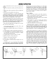
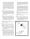
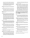
Select the back panel, the AC line cord, and the plas-
tic strain relief. Separate the two conductors at the
end of the cord for 2”. Cut 3/4" off of one conductor.
Strip both ends the usual ¼", and tin the strands to
secure
them. Six inches from the longer end make a
sharp V in the cord by bending it back on itself.
Install the strain relief as shown in the drawing. The
small end of the strain relief is nearest the stripped
ends. Crimp the two halves of the strain relief
together around the cord with heavy pliers to par-
tially form it before insertion into the back panel.
10
Then grip the larger portion of the strain relief with
the tips of the pliers, squeeze it tightly, and insert the
end of the cord and the strain relief through the panel
hole from the outside. Note that the hole has a flat on
one side, and the strain relief is installed so that the
cord is horizontal.
This is the most difficult step in the kit. Patience, and
a friend’s help, if available, will make this job easier.
Safety requirements dictate that this be a tight fit.
Some persons might find it helpful to bolt on a side
piece (with the flanges out) to add rigidity to the
back panel, as well as a support to press against the
back panel while you squeeze the strain relief and
pull the line cord through. The fixture snaps into pos-
ition when it is
fully
inserted. Remove the side piece
if you attached it.
20
0
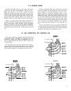
Select the power transformer and 2 sets of #6
hardware. Install the transformer next to the line
cord so that the leads are in the lower comer below
the strain relief.
21
0
Select the 4 AC sockets. Snap these into the back
panel holes from the outside.
22
0
Select the PC-12 circuit board assembly and the 2 flat
cable interconnecting assemblies. Plug one end of
each cable onto the pin connectors at the top of the
board so the cables extend past the back of the
board. The marked edge of the cable is not signifi-
cant. Now check socket J1 to make sure it does not
contact the stub of wire at hole A.