


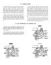

23 [7 Select the 6 black 5/8" screws, the 6 spacers, and 6
small nuts. Insert the screws from the outside of the
back panel at the locations nearer the center of the
panel (not in the end holes marked “Grounds”).
Install a spacer on each screw and tighten them.
Place the PC-12 assembly in position
so that its two
screws pass through the end holes. Install the nuts
on the black screws, and tighten them.
24
0
Select the 2 small nuts and the 2 knurled thumb nuts.
Install a nut on each of the Ground screws, making
sure the lockwasher surface is tight against the
panel. It must cut through the painted surface to
make a chassis ground connection . Then add the
thumb nuts.
25
0
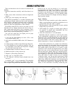
With a pair of pliers, carefully twist the 8 lugs on the
AC outlets counter-clockwise l/6 turn, or about
60º.
This will enable a wire to be passed horizontally
through these lugs.
26
0
Cut a
2¼”
piece of the bare buss wire. Slide it
through lug #2 of AC outlet B and connect it to lug
#l and to lug #3. Solder lugs 1 and 2.
27
0
Cut a 3%” length of bare wire. Slide it through AC
outlet lugs #6 and #7, and connect it to lug #5 and to
lug #8. Solder lugs 5,6 and 7.
28
0
Prepare a 13” length of white wire. Connect one end
to AC outlet C, lug
#3.
(S-2). Place this wire over the
top of the transformer.
29
0
Prepare a 13” blue wire. Connect one end to outlet D
lug #4. Place this and the following wire over the
transformer.
30
0
Prepare a
12½”
length of yellow wire. Connect one
end to outlet D lug #8.
31
0
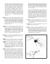
Select the two side pieces, the rubber grommet, and
4 sets of #6 hardware. Install the grommet in the side
piece location adjacent to the power transformer
when the flanges bend towards the outside of the
unit. Before bolting this piece in position, pass the
line cord through the grommet from the outside, and
under the transformer. From the inside thread the 3
wires which come from the AC outlets and over the
top of the transformer out through the grommet.
Fasten both side pieces to the back panel.
32
0
Connect the shorter line cord conductor to outlet D
lug #8. (S-3). Connect the other conductor to lug
#4.
(S-2).
33
0
Join the front and rear halves of the preamp so that
the tabs on the main board rear bracket ate outside
the side pieces. Select 2 sheet metal screws and fas-
ten the bracket tabs to the side pieces.
34
0
Plug the two flat wire assemblies onto the pin con-
nectors on PC-14.
35 IJ Prepare a 1%” piece of white wire. Connect one end
to the rear lug of the power switch. (S). Connect the
other end to eyelet Y of PC-14, nearest the fuse. (S).
All eyelet connections should be soldered on the
bottom of the board for secure connections.
36
q
Select the white wire from the tear grommet. Con-
nect it to eyelet W on PC-14. (S).
37
0
Select the blue wire
from
the grommet. Connect it to
the side lug of the power switch. (S).
38
0
Select the yellow wire. Connect it to eyelet T on
PC-14. (S).
The transformer leads may be shortened as desired for
neatness, but if there is any possibility that the transformer
may be connected for a different line voltage for use out-
side the USA, be sure to leave each lead long enough for
any alternative connection. We suggest that these leads be
made just long enough that they can be twisted together for
neatness, and placed outside the end piece where they can
be later secured with a wire tie.
39
0
Connect the Red-Yellow lead to eyelet A in the tear
comer of PC-14. (S).
40
0
Connect the two Red leads to eyelets B and C along
the rear edge of the board. Solder both.
For 120 volt wiring as in the USA, the following lead con-
nections are to be used. Refer to the alternative line vol-
tage diagrams in the manual for other line voltages.
41
0
Connect each lead as follows and solder:
Brown/White to eyelet D
Black/White to eyelet E
Brown/Red to eyelet F
Black/Red to eyelet M
Brown to eyelet R
Black to eyelet
S
42
0
Connect the short black wire from the forward lug of
the phone jack to eyelet G2. (S).
43
0
There are two groups of wires connected to the
phone jack under PC-14. The red and green wires
which connect to lugs 2 and 3 (these ate the lower
lugs, adjacent to the circuit board edge) are to be
connected to the upper (left channel) holes P and Q
on the back panel circuit board PC-12, adjacent to
the line outputs. Make certain you have the correct
group. The black
wire
is not connected to the board.
Instead, keep it twisted with the other wires until it
is close to the board, then wrapped tightly around
the red and green pair. Make
sure
no bare
wine
pro-
trudes from the black insulation. Connect the red
11