


wire to hole Q, which is between the center lugs of
Jll and 512. (S). The wire should not protrude sig-
nificantly beyond the front surface of the board to
avoid coming in contact with a connector. To assure
a good solder connection, bare wire should be visi-
ble on the circuit side of the board.
Connect the
green wire to hole P in like manner. (S).
44
0
At the rear of the phone jack, connect the black wire
from the first group (lugs 2 and 3) to PC14 eyelet G3.
(S).
45
[7 Select the other group of three wires, and connect the
black wire to PC- 12 hole T. (S). Connect the red wire to
hole S between Jl 11 and J112. (S). Connect the green
wire
to hole R. (S). Make sure the wires do not protrude
significantly beyond the outside surface of the board.
46
0
Connect the black wire of the second group to PC14
eyelet G1. (S).
47
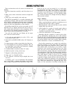
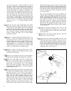
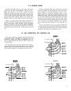
13 Select the 2 red LEDs. To install these with correct
polarity, observe the tiny ‘flat’ on the LED flange which
marks the cathode lead. This must he towards the near
end of the PC- 14 board, or Phono switch S 1, when the
LED is attached to the front, near the edge. When the
nipple of the LED is pointed toward you, with the flat on
the left, bend the leads (together, with long-nosed pliers)
upward at a right angle, so the bend will be 7/10” from the
back surface of the LED (about ¾”). Solder the LEDs to
the front holes on the under side of PC-14 with the bent
portion of the leads emerging on the top side. Each LED
protrudes through the front sub-panel hole. Solder both
leads on each LED.
48
0
Cut two ½” lengths of the black plastic shrink tubing.
Slide a piece of tubing over each LED from the front, so
only the nipple of the LED protrudes. Shrink the tubing
around the LED body by holding a lighted match near the
tubing. This will prevent back light from reflecting on the
sub-panel.
49
0
Select the two flat knobs, 2 set screws, and the smal-
ler L-shaped Allen wrench. Place a screw on the end
of the wrench and thread it into each knob. Install
these knobs on the switch shafts above the LEDs.
The set screw should engage the flat on each shaft.
50
0
In like fashion install the remaining set screws in the
4 round knobs, and fix them to the flatted shafts on
the other controls.
5 I
0
Taking care not to use excessive force, install the 6
black pushbuttons on the switches.
52
c
I Select a pair of end caps-either the standard ones,
or those for rack mounting-and the black front
panel extrusion. Place the front panel in position,
taking care to insert the LEDs into their holes, and
check for sufficient clearance around each knob. It
is possible to shift the phone jack bracket slightly, or
the mounting of an individual control (by resolder-
ing) if necessary for correct alignment. Slip each end
cap into the slots of the front panel. Select the 4 cap
screws and nuts, and secure the end caps with the
large Allen wrench.
53
0
Install the appropriate loading capacitors at the pairs
of holes identified E, F, G and H below the phono
input sockets on the back panel board. The correct
choice is discussed in the Additional Information
section of this manual. In lieu of more specific in-
formation, we suggest the 120 pF values at E and G
for Phono 1, and the 220 pF values at F and H for
Phono 2. Bend one lead around the capacitor so it is
parallel with the lead at the opposite end. The leads
should extend more than 1%” from the body, but must
not be longer than
%“, or they might touch the metal
back panel. Plug each into adjacent pairs of holes.
Now check to make sure that there are no strands of power
transformer leads, or the line cord, that are unsoldered. Where
the line cord passes under the transformer, make sure it is
clear of the screw hole in the back panel flange.
Check that a
1/10
ampere
(lOOmA)
fuse is installed in the PC-14 clips, and
that the Red/Yellow transformer lead connects to the corner
eyelet A.
54 q A wire tie can secure the transformer leads to the
side piece through the slot behind the PC-14 bracket.
These ties can be used only once, and lock securely
when the tail is pushed through the head end from
the flat side. Cut off the excess after pulling it tight.
55
0
The two groups of output leads from the phone jack
should be positioned at least 1” in from the side
piece, and straight to the rear of the PC-14 board;
then kept close to the bracket. A wire tie is
suggested at the rear comer. You may wish to use the
3rd tie on the wiring to the AC sockets, or on the
output leads near the back panel.
56
0
With 6 of the sheet metal screws, install the bottom plate.
The 2 large holes should he near the phono inputs at the
rear.
57
0
Place the 4 rubber feet in the corners of the bottom
plate. They are self adhesive when you remove the
paper backing.
58
0
Slide one piece of the U-shaped long plastic grommet
onto the top flange of the front sub-panel. The other piece
goes on the top flange of the back panel.
59
0
Check to make sure that the flat ribbon cable as-
semblies are up close to the top of the unit, away
from the circuit board, and slide the cover on from
the tear. Secure it with the 4 sheet metal screws.
60
17 Affix the self adhesive serial number label to the
center rear of the bottom.
You may wish to secure the smaller Allen wrench for the
knobs to the bottom of the unit with tape.