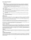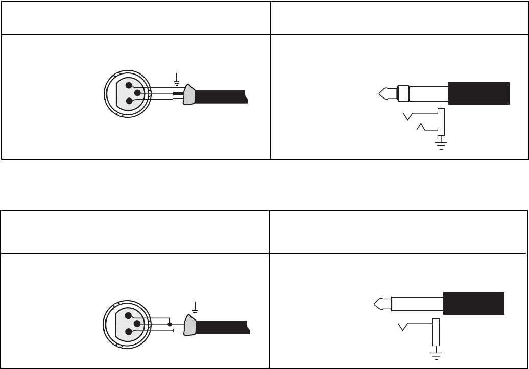
XLR Balanced Input
Check output of source unit for proper signal polarity
1/4" TRS Balanced Input
Check output of source unit for proper signal polarity
Pin 1 = GND
Pin 2 = (+)
Pin 3 = (–)
INPUT FROM
SOURCE
Tip = (+)
Ring = (–)
Sleeve = GND
INPUT
FROM
SOURCE
Many popular mixers use unbalanced outputs and can be used with the Balanced inputs. To minimize residual
ground noise, we recommend using twisted pair cable or short cable lengths in this type of configuration.
XLR Unbalanced Input
Connect (–) and GND (shield) terminals at
both ends
of cable to
prevent unstable amplifier operation
1/4" TRS Unbalanced Input
Pin 1 = GND
Pin 2 = (+)
Pin 3 = GND
INPUT FROM
SOURCE
Tip = (+)
Sleeve = GND
INPUT
FROM
SOURCE
1
2
3
GND
–
+
1
2
3
SHIELD
+
SHIELD
SHIELD
+
–
+
UNBALANCED INPUT
The unbalanced inputs use conventional RCA phone jacks. Set the BALANCED/UNBALANCED switch to the
UNBALANCED position to use these jacks.
BALANCED INPUT
The input jacks located on the back of the amplifier are dual function connectors which accept 1/4" Phone (Tip
Ring Sleeve) or XLR plugs. The 1/4" Phone jack is connected according to conventional usage. The XLR jack is
connected according to the IEC and AES standard.
OUTPUT CONNECTIONS
The speaker output connectors are dual binding posts. These binding posts will directly accept 12 AWG wire
or banana plugs and are spaced on 3/4" centers to accept dual banana plugs.
MONOPHONIC USE
For systems with high power requirements, the amplifiers can be configured for single channel bridged mono
operation. To bridge the amplifier, set the rear panel Mono/2 Ch switch to the Bridged Mono position. Only
the Channel 1 input and level control is used. The speaker is connected to the RED output binding posts.
– 4 –


