


T ABLE OF CONTENTS
SAFETY PRECAUTIONS ........................................................................................................................................... i
PERFORMANCE SPECIFICATIONS ......................................................................................................................... ii
INTRODUCTION ................................................................................................................................................... 1
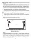
INSTALLATION
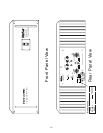
Front/Rear Panel View ...................................................................................................................................... 2
Location ........................................................................................................................................................... 3
AC Line ............................................................................................................................................................ 3
Input................................................................................................................................................................. 4
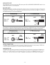
Balanced Input: 1/4" Tip Ring Sleeve.......................................................................................................... 4
Balanced Input: XLR................................................................................................................................... 4
Unbalanced Input ...................................................................................................................................... 4
Unbalanced Source with Balanced Input ................................................................................................... 4
Output Connections ......................................................................................................................................... 4
Monophonic Use.............................................................................................................................................. 4
OPERATION
Power Switch ................................................................................................................................................... 5
Input Switch ..................................................................................................................................................... 6
Ground Switch ................................................................................................................................................. 6
Mono Switch .................................................................................................................................................... 6
Load Fault Protection........................................................................................................................................ 6
Warm Up ......................................................................................................................................................... 6
Cleaning and Maintenance ............................................................................................................................... 6
PC Board Layout............................................................................................................................................... 7
Schematic Diagram .......................................................................................................................................... 8
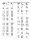
Parts List ......................................................................................................................................................... 10
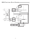
9505 Functional Block Diagram ..................................................................................................................... 12
TECHNICAL INFORMATION
Theory and Operation of trans•
nova ..............................................................................................................
13
Circuit Implementation ................................................................................................................................... 13
Calibration ..................................................................................................................................................... 14
Common Mode Rejection ........................................................................................................................ 14
Bias .......................................................................................................................................................... 14
WARRANTY ......................................................................................................................................................... 15