


INTRODUCTION:
Congratulations on purchasing a Gemini TT-01MKII belt drive manual
turntable. This state of the art turntable includes the latest features.
Prior to use, we suggest that you carefully read all the instructions.
FEATURES
• +/-10% Variable pitch slider
• Solid aluminum platter
• Straight tonearm for superior tracking
• Fully adjustable counter weight & anti-skating controls
• Dual speed RPM (33/45)
• LED Illuminated soft touch start/stop & RPM buttons
• Removable head shell
• CN-1000 cartridge & felt slipmat included
• RCA & ground cables
PRECAUTIONS:
1. Read all operating instructions before using this equipment.
2. The apparatus should not be exposed to dripping or splashing, and no
objects filled with liquids such as vases should be placed on the appara-
tus.
3. To reduce the risk of electrical shock, do not open the unit. THERE
ARE NO USER REPLACEABLE PARTS INSIDE. Please contact the
Gemini Service Department or your authorized dealer to speak to a qual-
ified service technician.
4. Tone Arm bearings are factory set and sealed. Any attempt at adjust-
ment will void the warranty.
5. Be sure that all AC power is OFF while making connections.
6. Cables should be low capacitance, shielded and of proper length.
Make sure that all plugs and jacks are tight and properly connected.
7. Always, begin with the audio level faders/volume controls set at mini-
mum and the speaker volume control(s) set to OFF. Wait 8 to 10 sec-
onds prior to turning up the speaker volume to prevent the transient
“POP” that could result in speaker/crossover damage.
8. DO NOT EXPOSE THIS UNIT TO RAIN OR MOISTURE.
9. DO NOT USE ANY SPRAY CLEANER OR LUBRICANT ON ANY
CONTROLS OR SWITCHES.
PARTS CHECKLIST:
Please make sure the following parts are included with your TT-01MKII:
Turntable unit..........................................................................................1
Turntable platter......................................................................................1
Slipmat....................................................................................................1
Counterweight.........................................................................................1
Headshell with cartridge.........................................................................1
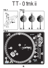
ASSEMBLY & SET-UP:
SEE FIG. 3 FOR PART NUMBERS AND LOCATIONS.
VOLTAGE SELECTION:
Rotate the PLATTER (2) until the VOLTAGE SELECTOR (3) (located on
the TURNTABLE BASE (1)) is visible through one of the platter holes.
Make sure that the VOLTAGE SELECTOR (3) switch is set to the cor-
rect voltage.
WARNING: IF YOU TRY TO OPERATE THE TURNTABLE WITH THE INCORRECT VOLTAGE
SETTING, IT CAN DAMAGE YOUR TURNTABLE.
ATTACHING THE TURNTABLE BELT:
The TURNTABLE BELT (4) comes attached to the underside of the
PLATTER (2) and the MOTOR SPINDLE (5) but can some times detach
in shipping. Rotate the PLATTER (2) and look through the platter holes
to check if belt detached. If the belt is not wrapped tightly around the
platter and the MOTOR SPINDLE (5), you need to reattach it.
1. Remove the platter and wrap the belt around the inner circle under the
platter. DO NOT STRETCH OUT THE BELT!
2. Replace the platter and rotate the PLATTER (2) until the MOTOR
SPINDLE (5) is visible, then fit your fingers in hole on the top of the
PLATTER (2), feel for and grab the rubber belt and attach to the motor
spindle.
3. Replace the locking washer.
TURNTABLE INSTALLATION:
1. Put the SLIPMAT (6) on the PLATTER (2).
2. Set the TURNTABLE BASE (1) on a flat, level surface free of vibra-
tion. Use the turntable feet to stabilize the unit horizontally.
3. Try to place the unit as far away from the speakers as possible.
4. Keep the unit away from direct exposure to the sun, heat, moisture or
dirt.
5. Keep the unit well ventilated.
CARTRIDGE INSTALLATION: (SEE FIG. 1)
Because all cartridges have their own designs, please refer to your
particular cartridge’s instructions to insure proper installation. If you are
using a pre-mounted or integrated cartridge, you can jump ahead to
HEADSHELL INSTALLATION:
1. Connect the lead wires to the cartridge terminals. For your conven-
ience, the terminals of most cartridges are color-coded. Connect each
lead wire to the terminal of the same color. Incase your cartridge is not
marked the positive leads are the ones on top negative below, left are
left, and right is right.
White (L+)........................................................................Left Channel +
Blue (L-).............................................................................Left Channel -
Red (R+).........................................................................Right Channel +
Green (R-).......................................................................Right Channel -
2. Mount the cartridge in the HEADSHELL (7) and tighten it with the
screws included with the cartridge.
HEADSHELL INSTALLATION:
Insert the HEADSHELL (7) into the front of the tubular TONE ARM (9).
While holding the HEADSHELL (7) firmly in a horizontal position, turn
the LOCKING NUT (8) counter clockwise until the HEADSHELL (7) is
locked in place.
COUNTERWEIGHT INSTALLATION: (SEE FIG. 2)
1. Slide the COUNTERWEIGHT (10) onto the rear of the TONE ARM (9)
with the numbered stylus gauge facing forward.
2. Twist the COUNTERWEIGHT (10) counter clockwise lightly, to screw
it onto the rear of the TONE ARM (9).
ADJUSTING HORIZONTAL ZERO (0) BALANCE
AND STYLUS PRESSURE:
1. Without touching the stylus tip, remove the stylus protector (if your
cartridge has a detachable one).
2. Release theARM CLAMP (12) and lift the TONE ARM (9) off the ARM
REST (13).
3. Counter clockwise advancement of the COUNTERWEIGHT (10) will
cause the cartridge side of the TONE ARM (9) to be lowered; turning it
clockwise will cause the opposite. Turn the COUNTERWEIGHT
(10)clockwise or counter clockwise as needed until the TONE ARM (9)
is balanced horizontally. You can easily tell this by watching for the point
where the TONE ARM (9) “floats” freely.
4. Place TONE ARM (9) on ARM REST (13) and lock it in place with the
ARM CLAMP (12).
5. With the TONE ARM (9) locked on the ARM REST (13), hold the
COUNTERWEIGHT (10) steady with one hand while rotating the STY-
LUS PRESSURE RING (11) until the numeral “0” on the ring aligns with
the center line on the TONE ARM (9) rear shaft. The horizontal zero (0)
balance should be completed.
(44)