


Fusion Intelpage IP Manual
Page 50 © CommtechWireless
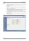
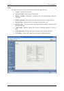
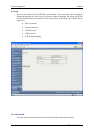
4.6 Transmitters
Thick steel and concrete, large magnetic and electric fields, and terrain and weather
conditions will affect transmitter efficiency, so you will need to test the coverage of your
local area transmitter at some stage of installation.
When you perform the test you should pay particular attention to the quality of the
messages that you receive on the test pager. If you receive corrupted messages then it is
possible that you will have problems sending messages to that region.
If you find that you are receiving corrupted messages then you should consider the
following methods for improving transmission quality:
• Move the antenna to a position that gives it a clear line of site to all areas you wish to
cover.
• Reduce the length of the cable connecting the aerial to transmitter.
• Use the appropriate coaxial cable to connect the aerial to transmitter which will suit
the length of the cable run. For example use RG213 for runs up to 20 meters and use
LDF440 for runs over 20 meters.
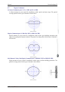
• Choose another type of antenna for the transmitter.
• Position the antenna in a higher location or use an antenna with a higher gain.
Increase the transmitter power. There are a number of objections to this method, such as
local restrictions on aerial power. In addition, doubling the transmitter power to the
aerial only gives an increase in range of a factor of 1:19 (fourth root).
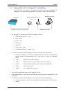
4.6.1 The installation of Multiple Transmitters and Aerials
For buildings in an area with good field strength outside but weak reception within,
possibly caused by shielding due to reinforcement in suspended slabs, metal plating and
other building materials:
• The supply lead to the aerial can serve as a radiator, effectively providing a 5 meter
(yard) range form the cable.
• The supply from open (leaky) coaxial cable as a line radiator lead to a 50 Ω terminator
(the cable is in effect the aerial).
4.6.2 VSWR
▲ WARNING: VSWR is a measure of impedance mismatch between the
transmission line and its load. The higher the VSWR, the greater the mismatch. A
high VSWR means some of the transmitted signal is being reflected at the antenna,
back down the coax line and back into the transmitter itself. If this value is too
high, the amount of power reflected back into the transmitter can damage the
transmitter. The minimum VSWR, i.e., that which corresponds to a perfect
impedance match is 1. It is essential that the VSRW of the antenna and coax
connected to the amplifier is set to 1.5 or better using a SWR meter. If this test is
skipped, permanent damage may result to the amplifier. Damage will also occur to
the unit if the amplifier is set to transmit if no antenna is connected to the unit. To
transmit without an antenna connected to the unit, use a dummy load capable of
handling at least 5 watts.