


HDMI 201 Tx/Rx • Installation and Operation
Installation and Operation, cont’d
2-26
HDMI 201 Tx/Rx • Installation and Operation
2-27
W
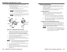
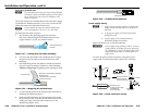
The two power cord wires must be kept separate
whilethepowersupplyispluggedin.Remove
power before wiring.
C
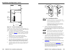
The length of the exposed (stripped) copper wires
is important. The ideal length is 3/16" (5 mm).
Longer bare wires can short together. Shorter wires
are not as secure in the connector and could be
pulled out.
N
Donottinthepowersupplyleadsbeforeinstallingin
the direct insertion connector. Tinned wires are not as
secure in the connectors and could be pulled out of the
connector.
Non-Decoraunitsonly—Use the supplied tie-wrap to strap
the power cord to the extended tail of the connector.
N
Yourtransmitter/receiverpairmayhaveshippedwitha
blue captive screw connector. This blue connector can be
plugged into either a blue or an orange power receptacle.
The blue connector does not have the extended tail or the
included tie-wrap.
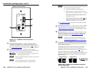
Snap the provided ferrite bead onto the DC power cable,
between the power supply and the HDMI unit’s connector.
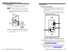
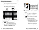
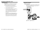
RS-232 connector wiring
Figure 2-25 shows how to wire the RS-232 connector for non-
Decora and Decora units.
Ground
Receive pin on connected unit
Transmit pin on connected unit
Connected RS-232
Device Pins
Tx/Rx
Pins
Rx
Tx
Figure 2-25 — RS-232 connector wiring
C
The length of the exposed (stripped) copper wires
is important. The ideal length is 3/16" (5 mm).
Longer bare wires can short together. Shorter wires
are not as secure in the connector and could be
pulled out.
N
Donottinthepowersupplyleadsbeforeinstallingin
the connector. Tinned wires are not as secure in the
connectors and could be pulled out of the connector.
N
TheRS-232connectorcanalsotransmitone-way
modulated infrared (IR) signals. See "Modulated IR
pass through" on page 2-32.
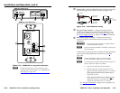
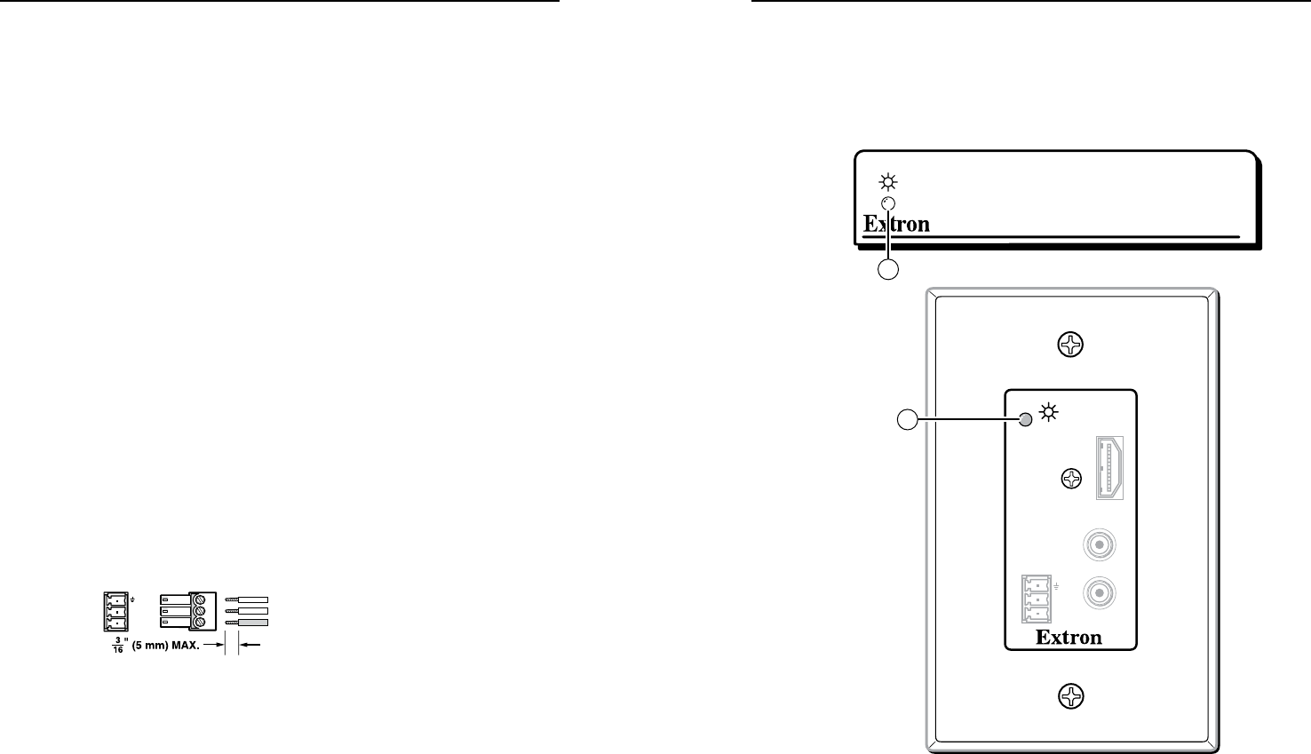
Operation
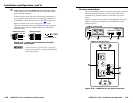
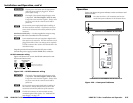
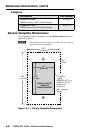
Figure 2-26 shows the power indicator on the non-Decora and
Decora models.
N
Two units are shown. All transmitter and receiver
models have power indicators in the locations shown.
HDMI 201
INPUT
Rx
Tx
RS-232
PASS THRU
AUDIO-R
HDMI
AUDIO-L
1
HDMI 201 Tx and HDMI 201 Rx Front Panel
HDMI 201 A D Tx and HDMI 201 A D Rx Front Panel
1
Figure 2-26 — Front panel indicators