


HDMI 201 Tx/Rx • Installation and Operation
Installation and Operation, cont’d
2-20
HDMI 201 Tx/Rx • Installation and Operation
2-21
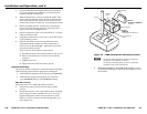
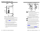
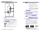
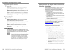
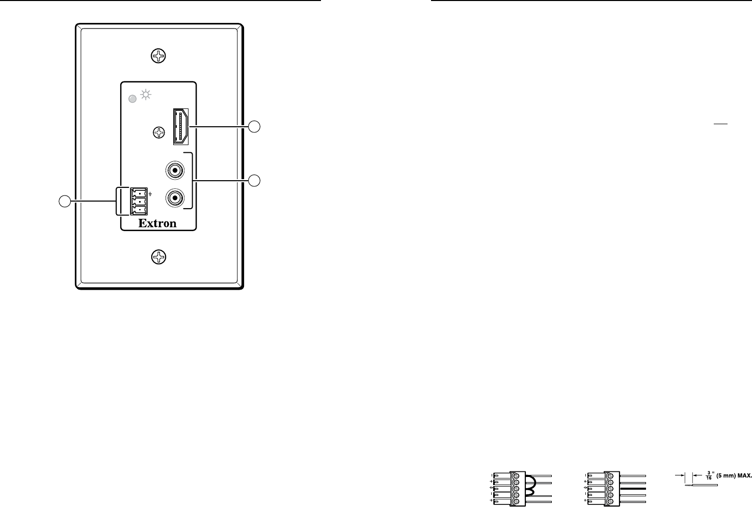
HDMI 201 A D Rx Front Panel
OUTPUT
Rx
Tx
RS-232
PASS THRU
AUDIO-R
HDMI
AUDIO-L
10
12
9
Figure 2-17 — HDMI 201 A D Rx front panel
connectors
g
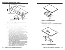
DCpowerinputconnector — Plug the included external
12 VDC power supply into either this 2-pole connector or the
power input connector on the transmitter (item
d
on page 2-17).
See "Power supply wiring," on page 2-25, to wire the connector.
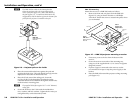
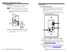
h
Receiverinputconnector— Connect one end of the two
separate TP cables from the transmitter output connectors (item
e
on page 2-17) to these RJ-45 female connectors.
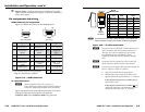
C
Do not connect these devices to a computer data or
telecommunications network.
N
Extron recommends 28AWG to 24AWG TP cable for the
RJ-45 connectors.
N
Connect transmitter output 1 to receiver input 1.
Connect transmitter output 2 to receiver input 2.
N
Ifnecessary,testforpropercableconnection(output1to
input 1, output 2 to input 2) as follows:
1. Plug both TP cables into the powered unit.
2. Momentarilyconnecteitherofthecablesonthe
opposite end into the unpowered unit‘s “2” connector.
If the unpowered unit’s Power LED is lit, the
connection is correct.
If the unpowered unit’s Power LED is not lit,
unplug the connector on the unpowered end and
connect the other cable to the “2” connector.
See "TP cable termination," on page 2-22, to properly wire the
RJ-45 connectors.
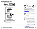
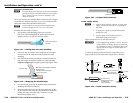
i
HDMIOutputconnector— Connect a display with an HDMI
input for display of the transmitted direct digital image. See
"HDMI connector pin assignments," on the next page, for pin
assignments.
j
RS-232connector—Connect a serial communications port to
this 3.5 mm, 3-pole captive screw connector for bidirectional
RS-232 communication. See "RS-232 connector wiring," on
page 2-26, to wire the connector.
N
TheRS-232connectorcanalsotransmitone-way
modulated infrared (IR) signals. See "Modulated IR
pass through" on page 2-32.
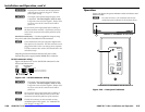
k
AudioInputconnector(HDMI201ADRx[Decora]only)—
Connect one end of a 5-wire audio cable to this 3.5 mm, 5-pole
direct insertion connector.
Connect the free end of the same cable to any compatibly
wired audio source unit, such as a switcher's output or a
HDMI 201 A D Tx (Decora) transmitter (item
f
on page 2-18).
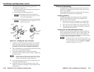
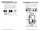
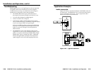
Figure 2-18 shows how to wire the captive screw audio
connector. Insert the wires into the appropriate openings in the
direct insertion connector. Tighten the screws on the side to
fasten the wires.
Tip
Sleeve
Sleeve
Tip
Unbalanced Input Balanced Input
Do not tin the wires!
Sleeve (s)
Tip
Tip
Ring
Ring
L
AUDIO
OUTPUT
R
L
AUDIO
OUTPUT
R
Figure 2-18 — Captive screw connector wiring for
receiver audio input