


HDMI 201 Tx/Rx • Installation and Operation
Installation and Operation, cont’d
2-22
HDMI 201 Tx/Rx • Installation and Operation
2-23
l
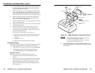
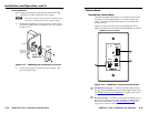
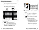
OutputAudio—Plug an audio device into this pair, left and
right, of female RCA connectors (gure 2-14) for an unbalanced
stereo audio signal.
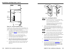
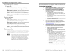
Pin assignments and wiring
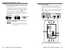
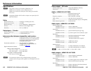
HDMI connector pin assignments
Figure 2-19 denes the pinout for the HDMI protocol.
Pin Signal
1
TMDS data 2+
TMDS data 2-
TMDS data 0–
TMDS clock- +5 V power
Hot plug detect
CEC control*
Reserved
(NC)
TMDS data 1+ TMDS clock+
TMDS clock
shield
SDA
DDC / CEC
Ground
TMDS data 2
shield
Pin Pin Signal Signal
2
713
41016
11 17
12 18
19
* CEC control on pin 13 is a proprietary
usa
ge, not the industry standard.
14
3
TMDS data 0-
TMDS data 0
shield
8
9
SCL
15
TMDS data 1-
TMDS data 1
shield
5
6
HDMI
HDMI
Type A Receptacle
Type A Plug
1
18 2
19
1
182
19
Figure 2-19 — HDMI connectors
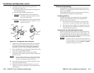
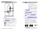
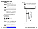
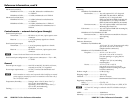
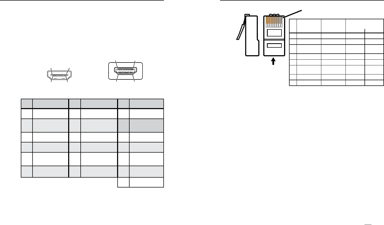
TP cable termination
N
RJ-45 termination with CAT 5, CAT 5e, or
CAT6cablemustcomplywiththeTIA/EIAT568Aor
TIA/EIA T 568B wiring standard for all connections.
Figure 2-20 details the recommended termination of TP cables
with RJ-45 connectors in accordance with either the
TIA/EIAT568A or the TIA/EIAT586B wiring standard.
5
Pin
1
2
3
6
7
8
4
N Terminate both ends of both cables identically, in accordance with
either the TIA/EIA T 568A or the TIA/EIA T 568B wiring standard.
Wire color
White-green
Green
White-orange
White-blue
Orange
White-brown
Brown
Blue
Data 0+
Data 0–
Data 1–
ID Clock–
Data 2+
Data 2–
Wire color
White-green
Green
White-orange
White-blue
Orange
White-brown
Brown
Signal
TIA/EIA T
586 A
TIA/EIA T
586 B
RJ-45 #1
ID Clock+
Data 1+Blue
CEC
HPD
RS-232
TX
+12 V
RS-232
RX
DDC data
Ground
RJ-45 #2
DDC Clk
Side
12345678
Insert
Twisted
Pair Wires
Pins:
RJ-45
Connector
Figure 2-20 — TP cable termination
N
Do not use Extron’s UTP23SF-4 Enhanced Skew-Free
™
A/V UTP cable to link the transmitter and receiver.
Skew-free A/V cable was designed for most Extron
TP transmitter/receiver applications, but the
HDMI201Tx/Rxdoesnotworkproperlywiththis
cable.
N
In order to fit in the junction box, the TP cables and
RJ-45 connectors should not have a boot installed.
N
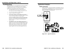
Ifnecessary,testforpropercableconnection(output1to
input 1, output 2 to input 2) as follows:
1. Plug both TP cables into the powered unit.
2. Momentarilyconnecteitherofthecablesonthe
opposite end into the unpowered unit‘s “2” connector.
If the unpowered unit’s Power LED is lit, the
connection is correct.
If the unpowered unit’s Power LED is not lit,
unplug the connector on the unpowered end and
connect the other cable to the “2” connector.