


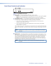
f
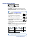
DIP switches —
SOG (Sync on Green) On/Off switch — Set this switch to the On (up) position to
enable SOG for RGsB video. Set this switch to the Off (down) position to disable SOG
for RGBS or RGBHV video.
Refresh switch — If the EDID Source switch (
d
) is in the Selector position and the EDID
select switch (
e
) is in position 1 through F position, set this switch either up or down to
select the refresh rate of the selected output (see table 1).
If the EDID Source switch (
d
) is in the Selector position and the EDID select switch is in
position 0, set this switch up to capture the EDID data from the monitor connected to
the Buffered Loop-through connector (
b
) (see Capturing a User-recorded EDID).
g
AC power connector — Plug a standard IEC power cord into this connector to connect
the interface to a 100 to 240 VAC, 50 Hz or 60 Hz power source.
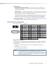
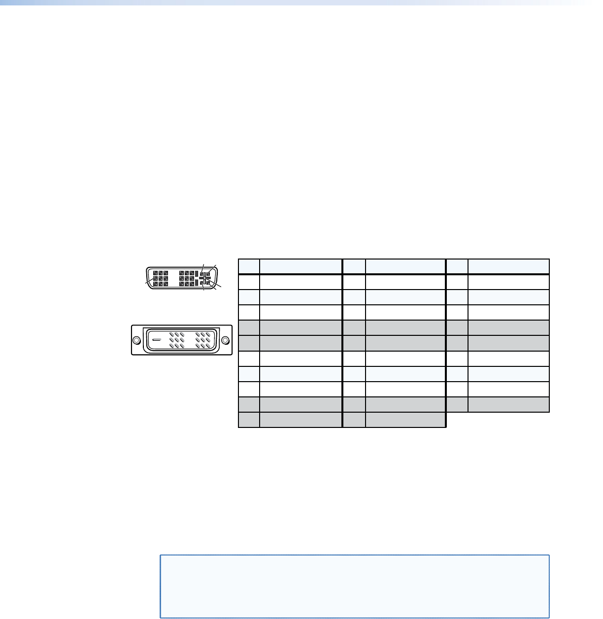
DVI Connector Pin Assignments
Figure 3 denes the DVI pin assignments.
Pin Signal
1
TMDS data 2–
TMDS data 2+
TMDS data 1–
TMDS data 1+
DDC clock
+5 V power
DDC dataTMDS clock+Ground (+5 V)
No connection TMDS clock–Hot Plug Detect
TMDS data 0–
TMDS data 0+
Spare
Spare
Spare
Spare
Spare
Spare
TMDS data 2 shield TMDS data 1shield TMDS data 0 shield
Pin PinSignal Signal
2
9
10
17
41220
51321
61422
71523
81624
18
31119
Male Connector
Female Connector
1
9
8
17 24
C3 C4
C1 C2
C5
C3
C4
C1
Analog Red Video
C2
Analog Green Video
C5
Analog Blue Video
Analog H. Sync
Analog Ground
Figure 3. DVI Connectors
DVI signals run at a very high frequency and are especially prone to bad video connections,
too many adapters, or excessive cable length. To avoid the loss of an image or jitter, follow
these guidelines:
• Do not exceed 16.4 feet (5 meters) on the input or buffered loop-through of the
interface.
• Limit or avoid the use of adapters.
• Use only approved DVI connectors.
NOTES: • Use only cables specically intended for DVI interfaces. Use of non-DVI cables
or modied cables can cause the DVI-RGB 200 to not operate correctly.
• The missing connectors on the included DVI cable (TMDS data 3, 4, and 5) are
not required for the single link of DVI-D data supported by the DVI-RGB 200.
These pins are grayed out in figure 3.
DVI-RGB 200 • Installation and Operation 4