


DVI DA Plus Series • Installation and Operation
Installation and Operation, cont’d
2-10
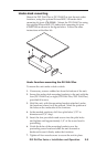
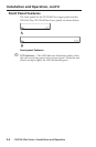
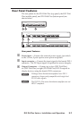
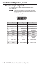
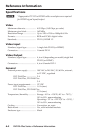
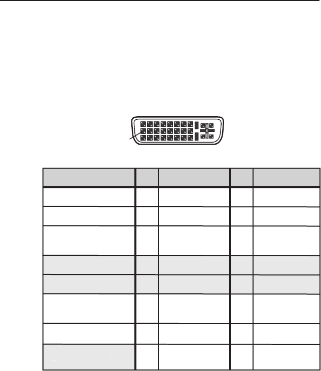
DVI connector pin assignments
The illustration below shows the pin assignments for the
DVI-I connectors.
N
Although DVI-I dual link connectors are used, these
distribution amplifiers are only compatible with single-
link DVI-D video signals.
Pin Signal
1
TMDS data 2–
TMDS data 2+
TMDS data 1–
TMDS data 1+
DDC clock +5 V power
DDC data TMDS clock+ Ground
TMDS clock–
Hot plug detect
TMDS data 0–
TMDS data 0+
Spare
Spare
Spare
Spare
Spare
Spare
TMDS data
2/4 shield
TMDS data
1/3 shield
TMDS data
0/5 shield
TMDS clock
shield
Pin Pin Signal Signal
2
9
10
17
4 12 20
5 13 21
6 14 22
7 15 23
81624
18
3 11 19
DVI - Female
1
9
8
17 24
Spare
8
S
p
are