P/2 DA2 WM/EC
Appendix
P/2 DA2 WM/EC Appendix
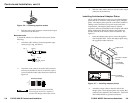
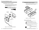
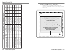
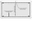
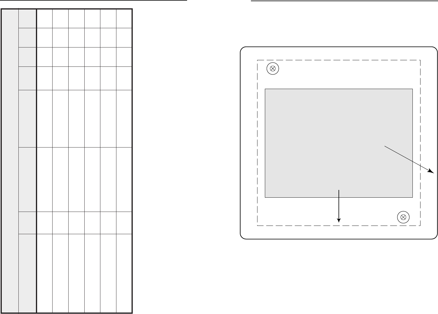
P/2 DA2 WM Mounting Template
Use this template as a guide for cutting the hole in the
installation surface (wall or furniture). This diagram is shown
at actual size.
The light gray area represents where
the P/2 DA2 WM enclosure (2.562” H x 3.437” W)
will be located against the rear of the
P/2 DA2 WM front panel.
The dotted line indicates the recommended
cut-out area (3.875” H x 3.80” W)
for the installation surface.
The solid, outer line (4.50” H x 4.60” W)
represents the outside edge
of the wall mounting bracket.
Appendix, cont’d
A-11A-10
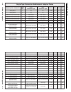
setalPretpadAlarutcetihcrArotcennoCepyTitluM
noitpircsedetalpretpadA
etalP
ezis
tnorF
epytrotcennoc
raeR
epytrotcennoc
#traP yarG
kcalB etihW
elamefCNB1dnaelamefoediv-S11
dnaelamefNIDinimnip-4
elamefCNB
elamefNIDinimnip-4
elamefCNBdna
701-0710-20-30-
elamefACR3dnaelamefoediv-S12
dnaelamefNIDinimnip-4
elamefACR
elamefNIDinimnip-4
elamefACRdna
701-0720-21-22-
elamefACR2dnaelamefoediv-S11
dnaelamefNIDinimnip-4
elamefACR
elamefNIDinimnip-4
elamefACRdna
701-0730-31-32-
elamefACR2dnaelamefCNB11
dnaelamefCNB
elamefACR
dnaelamefCNB
elamefACR
801-0710-11-12-
dnaelamefCNB1
kcajoeretsinimmm5.31
1
dnaelamefCNB
kcajoeretsinimmm5.3
dnaelamefCNB
spucredlos3
801-0720-21-22-
dnaelamefACR1
kcajoeretsinimmm5.31
1
dnaelamefACR
kcajoeretsinimmm5.3
dnaelamefACR
spucredlos3
901-0710-20-30-


