P/2 DA2 WM/EC
Controls and Installation
P/2 DA2 WM/EC
Controls and Installation
2-10 2-11
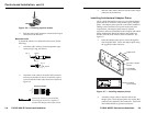
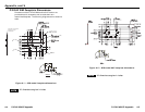
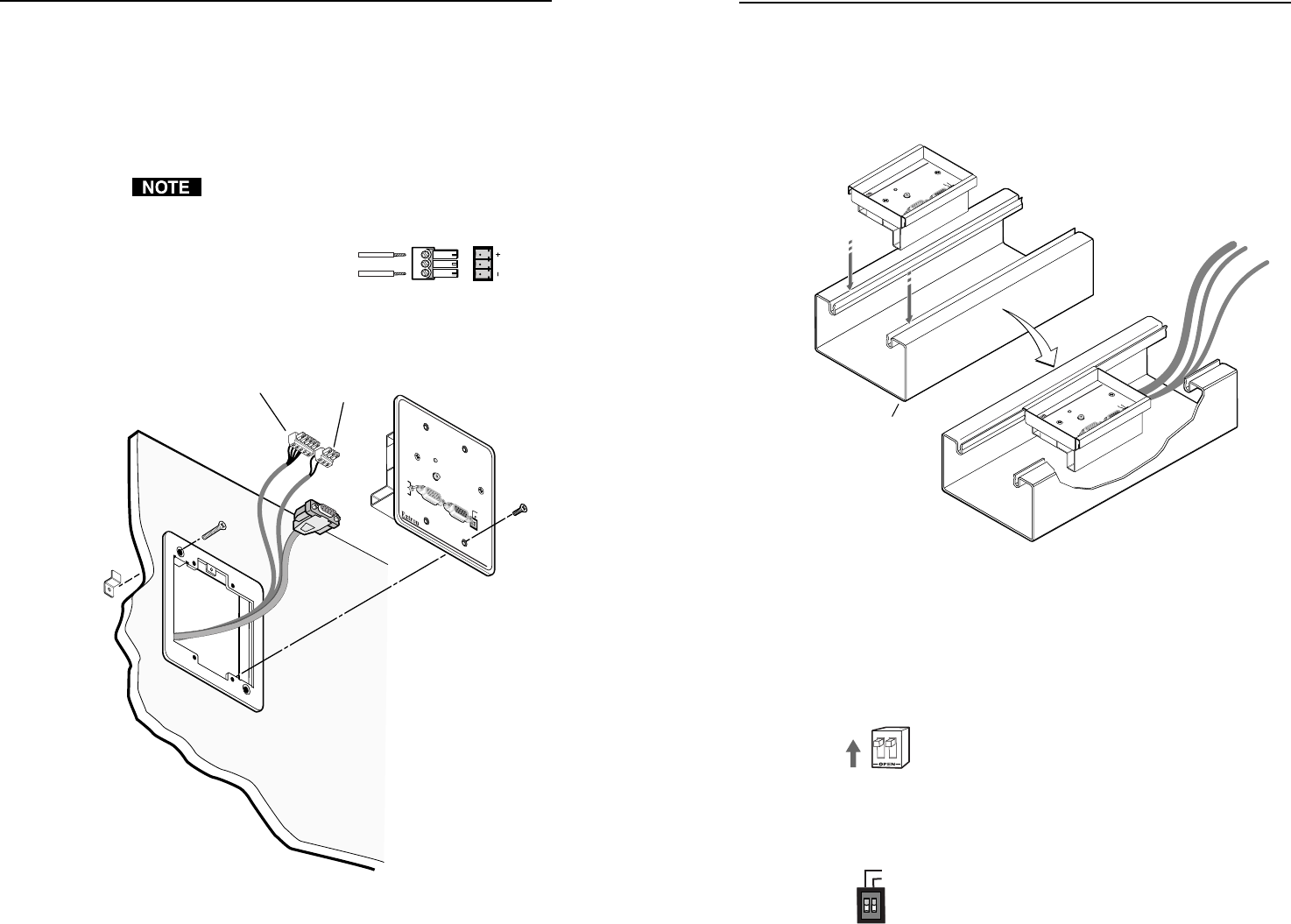
P/2 DA2 EC Euro Channel installation
Once the input and output cables have been connected and
tested on the P/2 DA2 EC, the distribution amplifier can be
easily installed in the Euro Channel. See figure 2-9.
Figure 2-9 — Euro Channel installation
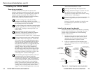
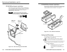
Setting the DIP switches
Two sliding-type DIP switches can be found on the
faceplate of the P/2 DA2 WM/EC.
To set the sliding-type DIP switches, slide the
switch to the on/closed or off/open position.
The two DIP switches provide proper ID bit termination for
a laptop computer that is not attached to a local monitor.
ID PIN 4 & ID PIN 11
ON — Set both pins to On if you are using the
P/2 DA2 WM/EC with a laptop
computer that is not attached to a local
monitor.
Controls and Installation, cont’d
ID PIN 4
ID PIN 11
INPUT
AUTO POWER
ID PINS
UNITY
GAIN/
PEAKING
100%
50%
11
4
AUDIO
BUFFERED
LOCAL MONITOR
WITH ADSP
TM
INPUT
AUTO POWER
ID PINS
UNITY
GAIN/
PEAKING
100%
50%
11
4
AUDIO
BUFFERED
LOCAL MONITOR
WITH ADSP
TM
P/2 DA2 WM
Euro Channel
P/2 DA2 WM
P/2 DA2 WM
INPUT
AUTO POWER
ID PIN 4
UNITY
GAIN/PEAKING
100%
50%
ID PIN 11
AUDIO
BUFFERED
LOCAL MONITOR
VGA Connector
Power (3.5mm
Captive Screw
Connector)
Audio (3.5mm
Captive Screw
Connector)
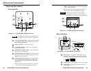
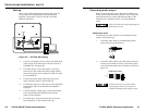
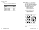
P/2 DA2 WM wallmount installation
Once the input and output cables have been connected and
the P/2 DA2 WM has been successfully tested, the faceplate
may be attached to the mounting bracket using the 4
supplied screws. See figure 2-8.
The center pole of the power input connector
contains no conductor. Connect the conductors to
the two outer poles only, exactly as shown here.
Figure 2-8 — Wall mounting the P/2 DA2 WM
12
Positive
Negative
N/C


