


Installing the Equipment
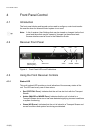
ETHERNET 1-2
TECHNICAL
EARTH
ASI/SDI OUT 1-2
CVBS
A
LARMASI INPUT
AC POWE
R
RF IN 1-4
AUDIO OUT (1)
1-2
IP OUT 1-2
CA
INTERFACE
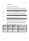
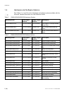
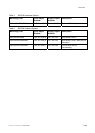
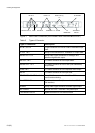
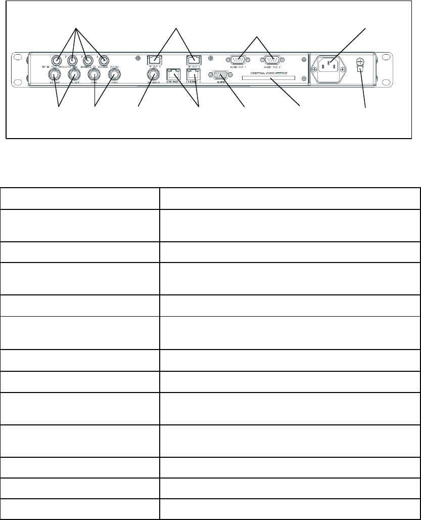
Figure 3 Rear Panel Connectors (RX8330/BAS with RX83XX/HWO/IP/OUT)
Table 6 Types of Connector
Type of Connector Description
RF IN 1,2,3 & 4
F-type connectors for DVB or DVB-S2 modulated input
feed.
IP OUT 1 & 2 8-way RJ-45 connectors for 1000BaseT IP output feed.
AUDIO OUT 1 & 2
9-way male D-type connectors for analogue and
balanced digital audio output.
ASI OUT 1 & 2
75 Ω BNC connector for ASI output feeds.
ASI/SDI OUT 1 & 2
75 Ω BNC connector for ASI or SDI (user selectable)
output feeds.
CVBS 1 & 2
75 Ω BNC connector for SD composite video output.
ASI IN
75 Ω BNC connector for ASI input feed.
ETHERNET / CONTROL 1 & 2
8-way RJ-45 connectors for 10/100BaseT Ethernet
control and monitoring.
CA INTERFACE
Conditional Access Slot (Common interface PCMCIA
CA interface).
ALARM 9-way male D-type connector for alarm signal output.
AC POWER IEC100-120 V AC / 220-240 V AC power input.
TECHNICAL EARTH Spade connector for unit technical earth.
EN/LZT 790 0008/1 R1A 2011-03-30
10 (40)