


Reference Manual
00809-0100-4690, Rev EA
March 2007
Rosemount 2088 and 2090
3-6
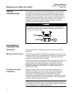
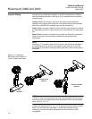
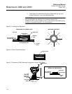
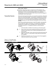
Impulse Piping Impulse piping configurations depend on specific measurement conditions.
Use the following information and Figure 3-3 as a guideline when installing
impulse piping.
Liquids: Make the line tap on the side of the pipe to prevent sediment
deposits from plugging the impulse line or transmitter. Mount the transmitter
level with or below the tap so gases vent into the process line.
Gases: Make line taps on either the top or the side of the process line. Mount
the transmitter level with or above the line tap so liquids drain into the process
line.
Steam: Make line taps in the side of the process line. Mount the transmitter
below the line tap to ensure that the impulse line remains filled with
condensate.
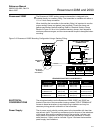
NOTE
Installing a “T”-connection with a shut-off valve in the impulse line between
the transmitter and the valve to the process line will allow you to vent the
transmitter to atmosphere, thereby enabling calibration without removing the
transmitter.
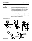
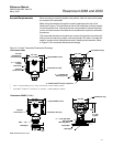
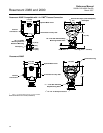
Figure 3-3. Transmitter
Mounting Configurations for
Liquids, Gases, and Steam
NOTE
In steam or other high-temperature services, the temperature at the process
connection must not exceed the process temperature limit of the transmitter,
which is 250 °F (121 °C).
In steam service above 250 °F (121 °C), fill impulse lines with water to prevent
steam from contacting the transmitter. Condensate chambers are not
necessary since the volumetric displacement of the Rosemount 2088
is negligible.
GAS
SERVICE
LIQUID OR STEAM
SERVICE
GAS OR LIQUID
SERVICE