


Reference Manual
00809-0100-4690, Rev EA
March 2007
Rosemount 2088 and 2090
3-14
With a meter installed
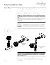
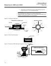
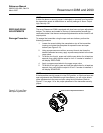
The failure mode alarm jumper is located on the LCD faceplate in the
electronics module side of the transmitter housing and is labeled ALARM
(See Figure 3-11). Do not remove the transmitter cover in explosive
atmospheres when the circuit is alive. Both covers must be fully engaged to
meet explosion proof requirements.
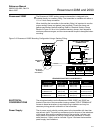
Transmitter Security After commissioning the transmitter, you may wish to protect the configuration
data from unwarranted changes. The transmitter is equipped with a security
jumper that can be positioned to prevent changes to the configuration data
(see Figure 3-11). The circuit board is electrostatically sensitive. Observe
handling precautions for static-sensitive components to avoid circuit board
damage.
When the transmitter security jumper is in the “ON” position, the transmitter
will not accept any “writes” to its memory. This means that configuration
changes (such as digital trim and reranging) cannot take place when the
transmitter security is on. To reposition the jumper, use the following
procedure.
1. If the transmitter is installed, secure the loop, and remove power.
2. Remove the housing cover opposite the field terminal side. Do not
remove the instrument cover in explosive atmospheres when the
circuit is alive.
3. Reposition the jumper. Avoid contact with the leads and the terminals.
Refer to Figure 3-11 for the location of the jumper and the ON and
OFF positions.
4. Reattach the transmitter cover. The cover must be fully engaged to
comply with explosion-proof requirements.
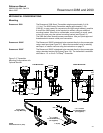
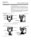
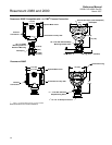
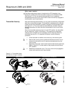
Figure 3-11. Transmitter Alarm
and Security Jumper Locations
.
Without LCD Meter Low Power without LCD Display
With LCD Meter Low Power with LCD Display
Alarm
Security
Alarm
2088A05A, 2088A05B
Security
Alarm
Security
Alarm
Security
2088A05, 2088A05C