December 2014
10
Quick Start Guide
Connecting the transmitter
Note
To comply with the CSA requirements, the transmitters must be powered from a
Rosemount 3490 Series Control Unit, or a class 2 or separate extra-low voltage
(SELV) source.
Other devices may reset if connecting the transmitter to a multi-drop system while the
loop is powered. De-energize loop to avoid devices being reset.
The 3107 and 3108 are two-wire, loop-powered transmitters accepting external
power supplies as follows:
12 to 40 Vdc in a non-hazardous area
12 to 30 Vdc in a hazardous area
Each transmitter is supplied with a factory-fitted PVC sheathed, two-core, shielded
cable for
communications and external power supply connections. There are no cable
conduit entries and no covers to remove. The cable may be cut to length on site or
may be extended using a junction box and suitable extension cable.
Installation in a non-hazardous area
1. Make sure that the power supply is disconnected.
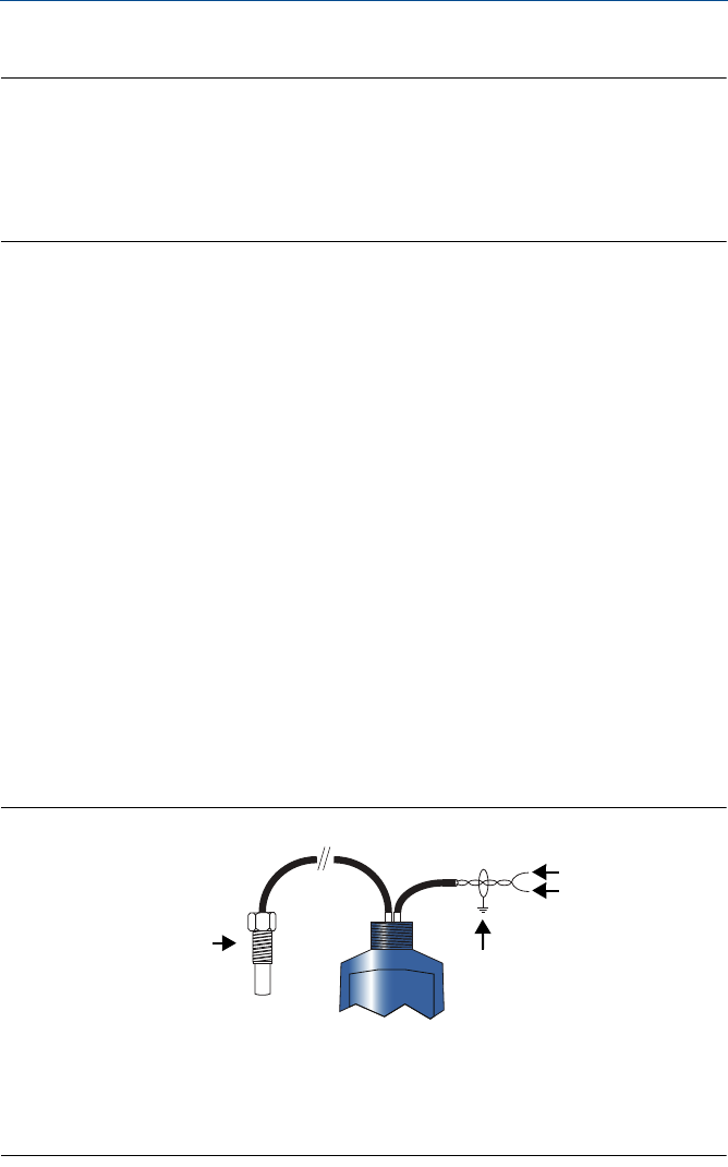
2. Connect the cable wires (Figure9), taking note of the required voltage of
12 to 40 Vdc for non-hazardous applications.
Installation in a hazardous area
When used with a Rosemount 3490 Series Control Unit, no additional safety barriers
are required. If powering the transmitter from any other source, ensure a suitable
Intrinsically Safe barrier is fitted in the non-hazardous (safe) area.
To connect the transmitter:
1. Make sure that the power supply is disconnected.
2. Connect the cable wires (Figure9), taking note of the restricted voltage of
12 to 30 Vdc for hazardous applications.
Figure 9. Wiring
A. Remote Temperature Sensor (3108 Only)
B. Black: 0 Vdc
C. Red: 12 to 40 Vdc (non-hazardous area), 12 to 30 Vdc from protective barrier (hazardous area)
D. Non-hazardous Area: Connect Cable Screen To Standard Ground (Earth) or
Hazardous Area: Connect Cable Screen To I.S. Ground (Earth)
B
C
D
A


