


50
DC-One Standard Configurations
Input A Input B Out 1
Link
Out 2
Link
Out 3
Link
Out 4
Link
Out 5
Link
Out 6
Source/Bandpass Source/Bandpass Source/Bandpass Source/Bandpass Source/Bandpass Source/Bandpass
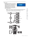
1 2-Way Stereo (+FR)
HPF HPF In A / Low L In A / Hi L In A / FR In B / Low R In B / Hi R In B / FR
PEQ PEQ
Parameters Parameters Parameters Parameters Parameters Parameters
GEQ GEQ PEQ PEQ PEQ PEQ PEQ PEQ
Delay Delay Hi-pass Hi-pass Hi-pass Hi-pass Hi-pass Hi-pass
Lo-pass Lo-pass Lo-pass Lo-pass Lo-pass Lo-pass
Delay Delay Delay Delay Delay Delay
Level Level Level Level Level Level
Limiter Limiter Limiter Limiter Limiter Limiter
Input A Input B Out 1
Link
Out 2
Link
Out 3
Link
Out 4
Link
Out 5
Link
Out 6
Source/Bandpass Source/Bandpass Source/Bandpass Source/Bandpass Source/Bandpass Source/Bandpass
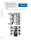
2 3-Way Stereo (+FR)
HPF HPF In A / Sub L In A / Lo-Mid L In A / Hi L In B / Sub R In B / Lo-Mid R In B / Hi R
PEQ PEQ
Parameters Parameters Parameters Parameters Parameters Parameters
GEQ GEQ PEQ PEQ PEQ PEQ PEQ PEQ
Delay Delay Hi-pass Hi-pass Hi-pass Hi-pass Hi-pass Hi-pass
Lo-pass Lo-pass Lo-pass Lo-pass Lo-pass Lo-pass
Delay Delay Delay Delay Delay Delay
Level Level Level Level Level Level
Limiter Limiter Limiter Limiter Limiter Limiter
Input A Input B Out 1
Link
Out 2
Link
Out 3
Link
Out 4
Link
Out 5
Link
Out 6
Source/Bandpass Source/Bandpass Source/Bandpass Source/Bandpass Source/Bandpass Source/Bandpass
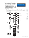
3 4-Way (+FR)
HPF HPF In A / Sub In A / Low In A / Mid In A / Hi In B / FR In B / FR
PEQ PEQ
Parameters Parameters Parameters Parameters Parameters Parameters
GEQ GEQ PEQ PEQ PEQ PEQ PEQ PEQ
Delay Delay Hi-pass Hi-pass Hi-pass Hi-pass Hi-pass Hi-pass
Lo-pass Lo-pass Lo-pass Lo-pass Lo-pass Lo-pass
Delay Delay Delay Delay Delay Delay
Level Level Level Level Level Level
Limiter Limiter Limiter Limiter Limiter Limiter
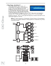
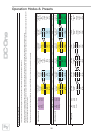
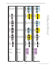
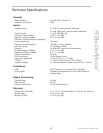
This chart describes the channel assignments and linking schemes of the different configurations available in the DC-One.
Channels and parameters indicated with the same colors are linked. When making a change to one channel or parameter this will also affect the linked parameter or channel.
A dashed box around a Lo-pass/Hi-pass filter combination in adjacent channels indicates that these filters are linked. Changing the filter type and frequency of the Lo-pass filter will automatically change the linked Hi-
pass filter on the adjacent channel and vice versa.
These links are only enforced while in Standard Edit Mode. When entering Full Edit Mode, all channel and parameter links are removed.
Parameters
Parameters
Parameters
Operation Modes & Presets