


20
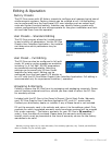
Run-time Mode
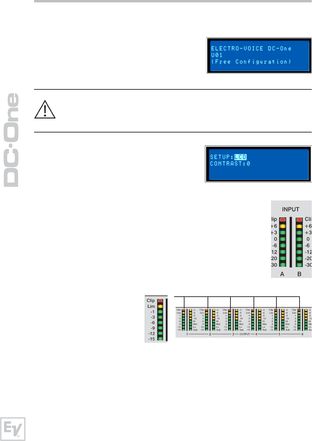
LCD Display
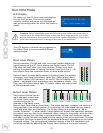
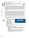
On power-up, the DC-One boots and displays
the run-time screen. The current preset
memory location and name are displayed as
well as the configuration on which the preset is
based.
Caution Before operating the sound reinforcement system, and any time a new preset is
recalled, check the configuration display to make sure that it is appropriate for your system
and that connections to your system are correct for the current configuration. Failure to do so
could cause unexpected results or damage to the system or its components.
The LCD display’s contrast can be adjusted in
the Setup Menu to accommodate different
viewing angles.
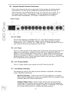
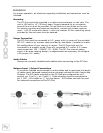
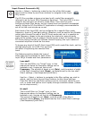
Input Level Meters
During operation, the left and right input level meters display the
signal present at the DC-One’s analog and Digital inputs. The DC-
One does not itself have input level controls. Proper input level
setting is accomplished by setting the output level from the (L / R)
bus outputs from the connected mixer or other audio source.
Optimal signal-to-noise performance is obtained when the nominal
(average), input level consistently lights the +3dBu (green) and /
or +6dBu (yellow) LED indicators. As the DC-One is a digital audio
device – and digital clipping produces very unpleasant results – the
Clip (red) LED should never light. If it does, reduce the output level
of the connected mixer.
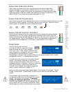
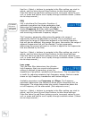
Output Level Meters
Each output channel has an
eight-segment output level
VU meter. Meter response
characteristics can be
selected in the Setup menu:
Normal Fast, Peak-Hold or Slow Decay. The yellow segment indicates that limiting is
being applied to the output channel. It is important to understand how the meters
work and what they are displaying. The Output Meters are displayed as “dB to
Limiter Threshold”. In other words, these meters will display the headroom between
the output level and the limiter threshold. When viewed in conjunction with the Gain
Reduction meters, this provides a complete display of level and headroom before
and after limiting has been engaged to allow system levels to be optimized. This also
means that the output metering will be displayed differently depending on the limiter
threshold setting. The red segments indicates clipping of the D/A converters and
should be avoided by adjusting the Output Level setting of the output channel.