


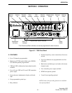
INSTALLATION AND DISASSEMBLY
2-3
November 1998
Part No. 001-7600-001
2. Route the red and black wires from the transceiver
to the battery. Connect the red wire to the positive
(+) terminal and the black wire to the negative (–)
terminal.
3. Plug the cable into the pigtail coming from the trans-
ceiver and reconnect the negative battery cable.
4. Install the antenna according to the manufacturer’s
instructions. The transceiver has a standard UHF
connector. Check VSWR. Reflected power should
be less than 4% of forward power (VSWR less than
1.5 to 1).
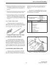
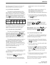
2.3.3 POWER CABLE FUSES
Each power cable wire is protected by a 20-
ampere fuse. These fuses are inspected and changed as
shown below. If a fuse blows, locate the cause if possi-
ble and replace it with one of the same rating.
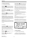
Changing 20-Ampere Power Cable Fuses
2.4 USING AN EXTERNAL SPEAKER
An external speaker can be plugged into the
external speaker jack on the back of the transceiver.
This speaker should have an impedance of 4-8 ohms
and a power handling capability of at least 3.5 watts.
The internal speaker is automatically disabled when a
speaker is plugged into this jack. The external speaker
jack is a standard 1/8-inch, two-conductor phone jack.
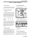
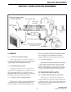
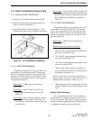
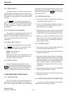
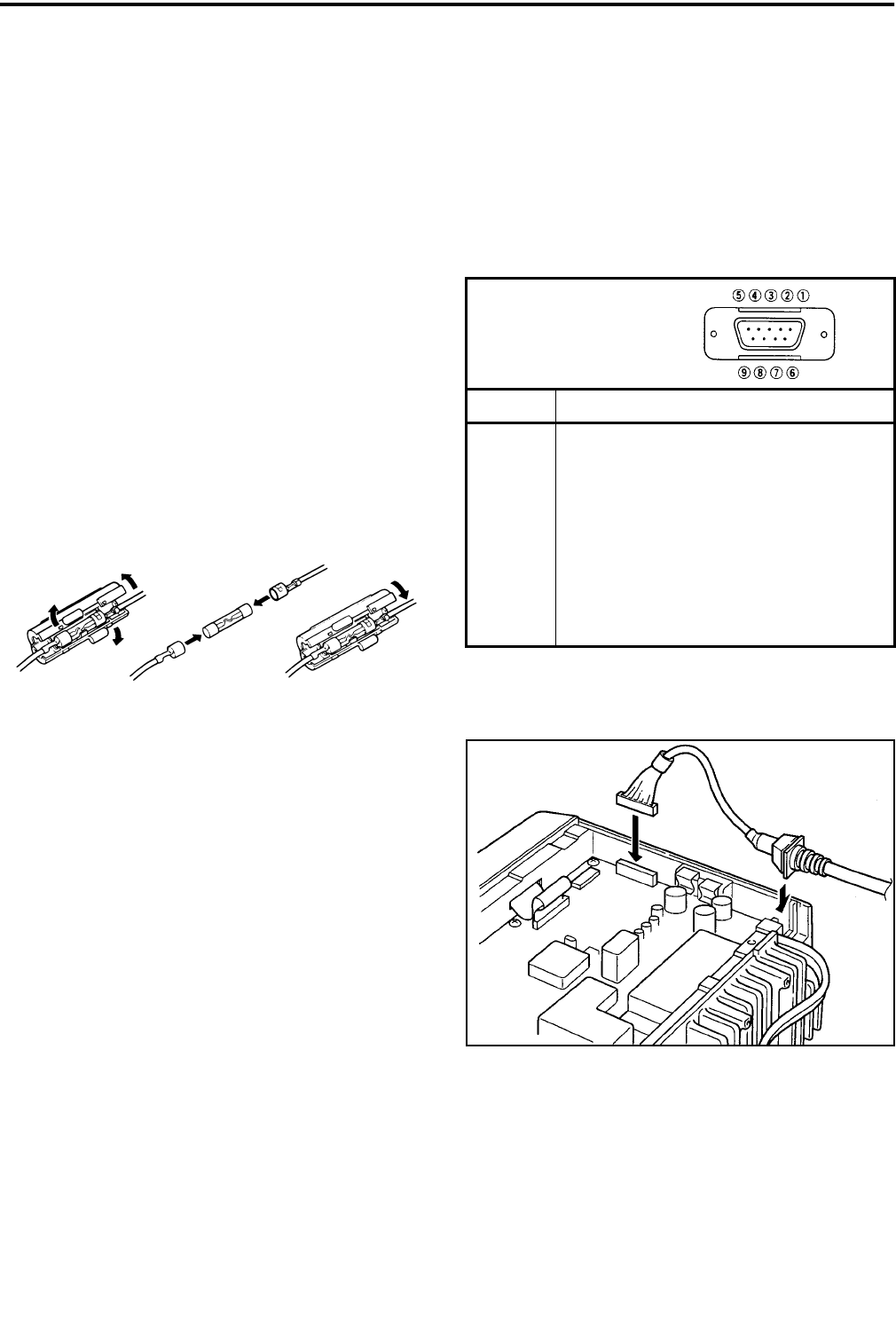
2.5 ACCESSORY CABLE INSTALLATION
Optional Accessory Cable, Part No. 585-7600-
027, can be used for connecting accessories such a
horn alert or modem to the transceiver. It also has an
input that can be used to control the backlight (see
Section 3.3.9). This cable is installed as shown in
Figure 2-3.
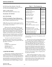
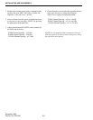
This cable has a standard DB-9 female connector
for interfacing to external equipment. The pin number-
ing and functions are as follows:
Figure 2-3 Accessory Cable Installation
DB-9 Pin Function
1 LCD backlight control in
2AF out
3 Detected AF out
4 Modulation in
5 PTT control in
6 Horn drive control out
7 AF ground
8 Detected AF ground
9 Modulation ground
DB-9 Female Connector
Outside View