NOTES: The Amp Gain, Max Voltage, and Listener Distance can be adjusted at any time by
selecting the CH function and the desired Output Channel then editing these parameters.
The HPF and LPF filters can be adjusted at any time by selecting the X-over function and the
desired Input Channel then editing these parameters.
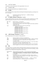
7.4.3 U-NET OUTPUT
Assign the summed, unprocessed sources to a U-Net output channel. This is useful for daisy-chaining an
analog or AES source signal to multiple UX8800 units.
7.4.4 NAME
Enter a name for the input channel, up to 16 alphanumeric characters.
7.5 CH (Output Channels 1 to 8)
Use the CH function to set the parameters for Output Channels 1 to 8 by selecting the 1 to 8 buttons.
7.5.1 SRC
Displays the Input Channel source for the selected output channel.
7.5.2 TYPE
Displays the model of the selected Greybox.
IMPORTANT !!
The Amp's Max Voltage and Amp Gain values you enter are CRITICALin order for the
UX8800 to provide the correct acoustic balance and limiter parameters. These values
must match the actual performance of the amplifier connected to each Greybox's output.
If these values do not match the performance, the loudspeaker or array may be voiced
incorrectly, be over protected, or be under protected.
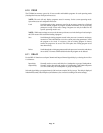
7.5.3 AMP GAIN
Scroll through and select the Amp Gain for the amplifier connected to that output channel. The range is
from 10 dB to 50 dB in 1 dB increments. This value is used by the UX8800 to determine the Output
Channel gain and limiter threshold setting.
The amplifier gain must be in dB, being 20 x log (input voltage / output voltage), the voltages being rms.
The value you enter MUST account for any gain or attenuation between the UX8800 output and the
amplifier input. Normally, the published gain specification for an amplifier is determined with its input
level control at maximum. Setting an amplifier's input level controls to less than maximum, as is often the
case to achieve good gain structure, changes the amplifier gain. In this case, the measure gain. Do not rely
on a level control's attenuation markings.
7.5.4 MAX VOLTAGE
Scroll through and select the Max Voltage (maximum rms voltage) for the amplifier connected to that
output channel. This value is used by the UX8800 to determine the limiter threshold setting.
The amplifier maximum voltage must be the rms level at clipping at the nominal impedance of the
loudspeaker, being the square root of (maximum watts at nominal Z x nominal Z). Determine this from the
amplifier specifications, calculation, or measurement.
Page 17


