


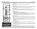
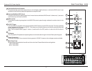
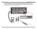
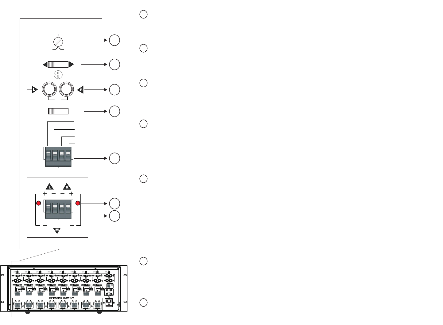
Level Controls
This feature adjusts the maximum desired output of the associated zone to prevent overpowering of small
speakers.
Note: This knob is by-passed when its zone selector switch(feature 2) is set to BUS.
LOCAL/BUS Switch
It switches the audio source between LOCAL and common BUS. In LOCAL mode, the zone acts independently
from the rest of system by only amplifying the information fed through the associated RCA inputs. In BUS mode,
that particular zone will amplify the signal fed through the main BUS input (page 11 - feature 9).
Audio RCA Input
Individual stereo RCA inputs to drive signal into associated zones. Both RCA’s, LEFT and RIGHT, are active
when the STEREO/MONO switch is set to MONO (feature 4). Thus, you can use either RCA inputs.
Note: This RCA input also serves as an Auto Signal Sensing whenever there is a signal greater than 12mV
present.
STEREO/MONO Selector
Switches the amplifier’s output between STEREO or MONO.
· In STEREO mode, the LEFT and RIGHT outputs operate independently at 75 Watts per channel at 4Ù
speaker load. Level, Gain, Auto Turn ON and MUTE are all common to both.
· In MONO mode, the LEFT and RIGHT stereo signals are summed internally for a single high power output.
You can drive two 4Ù speakers in this mode or a single 4Ù Bridged for maximum power of 150WRMS. Also, if
the source is already a mono signal, you may use either RCA, LEFT or RIGHT.
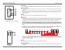
Keypad/Zone Connector
With four (4) removable conductors (IR IN, STATUS, GROUND and CI–Control Input), these screw type
connector accepts wire sized from 24 to 12 AWG. We recommend using the CAT5, CAT5E, CAT6 or CAT6E
wires.
· IR IN – receive all types of IR signal transmitted through the Earthquake Keypad. It allows Volume up/down
and mute function at the local amplifier. Also, it allows most IR signal to pass through the four built-in IR
repeaters of the Cinénova 16IR (page 11 - feature 12).
· STATUS – this connector delivers DC signal to the Keypad’s LED status indicator when the associated
amplifier is ON.
· GROUND – for the Keypad.
· CI – Control Input is the communicator line used to control amplifier’s ON/OFF (Mute) status manually.
Fault Fuse Indicator (FFI)
This LED indicates the safe operation of the amplifier’s internal circuit for the associated zone. Under normal
condition, this LED is off. When it is lit, the fuse on the internal circuit of that associated zone is blown, usually
due to a shorted circuit. Simply replace with the same size fuse. For your convenience, we’ve included four (4)
additional fuses with every amplifier.
Speaker Terminals
This screw type connector with four (4) removable conductors accepts wire sizes from 16 to 12 AWG. Observe
the Polarity printed on the terminal. Observe the printed instruction above and below the Speaker terminal.
1
2
7
3
4
5
6
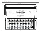
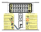
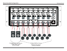
Rear Panel Map - LOCAL
1
2
3
4
5
6
7
STATUS
GROUND
IR IN
BUS
MONO
CI
FFI
0.2V3V
LEVEL
1V
BRIDGE
1
STEREO
LOCAL
FFI
L
M
R
L
M
R
L
M
R
L
M
R
L
M
R
L
M
R
L
M
R
L
M
R
SPEAKER OUTPUT
L
L
L
L
L
L
L
L
R
R
R
R
R
R
R
R
L
R
L
R
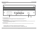
FUSE
110-120VAC-60Hz
220-240VAC-50Hz
Earthquake Sound
10