


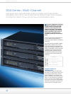
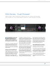
dsa se ri es - Mu l t i -CH a n n e l
41
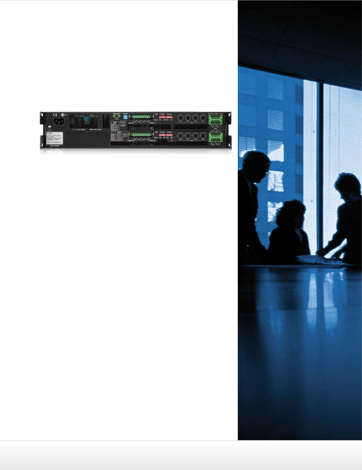
Depending upon the application,
each channel can be switched in-
dividually even in high-impedance
mode (HZ) in order to drive 70
Vrms or 100 Vrms loudspeaker
lines directly without an output
transformer (Direct Drive).
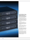
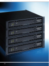
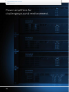
The power output by the DSA
multi-channel power amplifiers is
(along with its thermal capacity)
limited only by their maximum
output voltage and maximum
output current, which means they
can drive any load between 2 and
10 ohms with their rated maximum
outputs of 500 W and 1000 W res-
pectively per channel.
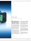
A corresponding encoder-circuit
is provided on the rear panel. In
addition, through VLD (Variable
Load Drive) in combination with
a RCM-810 remote control module,
it is possible to define freely
which output power should be
made available at which load in
the frame described above in the
channel in question: e.g. Channel
A = 350 W into 2.6 Ω; Channel B =
500 W into 8 Ω; Channel C = 200 W /
100V etc.
The fact that an output trans-
former has been dispensed with
the highly efficient Class-D power
amplifiers and switching power
supply yields an extremely attractive,
environment- and resource sparing
amplifier. For applications involving
mandatory galvanic separation of
the connected loudspeakers in
accordance with EN 60849 and
IEC 60364 separate transformer
modules are available, optionally.
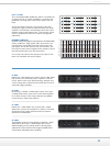
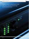
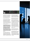
Input level controls on the rear
panel as well as LED meters and
control indicators on the front
panel offer a high degree of user
comfort. It goes without saying
that all protective circuits and dy-
namic limiters (as is the case with
in all DYNACORD power amplifiers)
are available in every channel. Using
the ON DELAY selector switch
on the rear panel of the power
amplifier, you can set the interval
of time by which the switching
on process should be delayed. In
Standby mode, the power consump-
tion of the device is reduced to a
minimum. Standby mode can be
activated via IRIS-Net or the POWER
REMOTE socket.
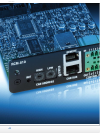
The Phoenix inputs marked IN-
PUT are electronically balanced.
Phoenix connectors are also provi-
ded for the power outputs.
The POWER REMOTE connector
makes the task of remote controlling
the power amplifier as well as
switching it on and off simple. For
further remote-supervision and
–control possibilities and integration
into IRIS-Net networks, an optional
remote control module (RCM-810)
is available.