


Dolby E Multichannel Distribution System User Manual DP572 Dolby E Decoder
4-5
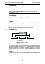
The state of the pins is normally high (internal pull up), and they detect a high-to-low
transition. A held contact closure between pins 7 and 9 (ground) or pins 8 and 9 is
required to activate a function. A low-to-high transition (i.e., a switch release) restores
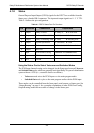
the External Standby setting. Table 4-2 shows the function of the two GPI pins on
the DP572.
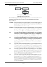
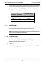
Table 4-2
Status port output routing mode selection
4.1.9 Digital Outputs
A maximum of eight channels of decoded audio are supplied on the four AES3 outputs.
A second electrically isolated output is supplied for each channel pair.
Note: The digital outputs are electrically separate, not passive loop-through connections,
so there is no need to terminate an unused output.
4.1.10 PCM Delay Output
Encoding delay is added to the PCM signal which is then transmitted from the PCM
Delay Out connector. The DSP subsystem calculates the delay equivalent to the main
channel latency and applies it to the PCM Delay Out. If PCM bypass mode is enabled,
the delay matches that of the bypass channel.
4.1.11 LTC Output
After de-multiplexing timecode information from the Dolby E stream, the DP572
provides a standard SMPTE LTC signal.
Ctrl in pin 8 Ctrl in pin 7
PCM Chan Config
Output Routing Mode
High High External Standby
High Low Voiceover
Low High Switched Out
Low Low Reserved