


Dolby E Multichannel Distribution System User Manual Common Dolby E Applications
2-3
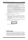
2.6 Postproduction
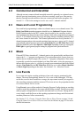
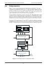
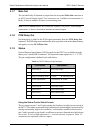
Figure 2-1 shows a typical postproduction configuration using Dolby E. The same
VRef black burst signal locks all units; an LTC signal slave-locks a digital multitrack
recorder to a digital VTR. The LTC signal is also sent to the DP571 LTC Input via the
loop-through connector on the multitrack. The DP571 and VTR have the same time code
signal to resynchronize the video and audio if they are separated.
Connect the DP571’s Main Out to channels 3/4 on the VTR. Although the Dolby E signal
could be recorded on either channel pair, using channels 1/2 for PCM stereo or Lt/Rt
allows use of the tape at facilities without a Dolby E decoder. It also allows audio repro-
duction from these tracks during jog and shuttle operations in which Dolby E is muted.
Connect the VTR’s output channels 3/4 to the DP572 decoder for confidence monitoring.
Headphones can be used to monitor any of the active channels. It is also possible to connect
the DP572’s Digital Outputs to a proper monitoring system to evaluate the entire mix.
Figure 2-1
Typical Dolby E system in a postproduction facility
DP571 Dolby E Encoder
DP572 Dolby E Decoder
1/2 3/4 5/6 7/8
L/R C/LFE Ls/Rs
Lt/Rt or SAP
LTC In
LTC Out
LTC In
Main
Ch. 3/4
Ch. 3/4
Main
VRef
VRef
VRef
VRef
Digital Outputs
Digital Inputs
To Monitor System
1/2 3/4 5/6 7/8
Headphones
Digital Multitrack Recorder
Digital VTR