


Dolby E Multichannel Distribution System User Manual
3-1
Chapter 3
DP571 Dolby E Encoder
3.1 Hardware Reference
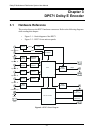
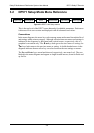
This section discusses the DP571 hardware connectors. Refer to the following diagrams
while reading this chapter:
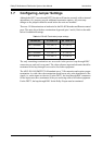
• Figure 3-1 – block diagram of the DP571
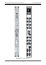
• Figure 3-2 – DP571 front and rear panels
Figure 3-1
DP571 Block Diagram
TC Receiver
VREF
Synchron.
Sample Rate
Converter
Sample Rate
Converter
Sample Rate
Converter
Microcontroller
Input Chan. 1/2
Input Chan. 3/4
Input Chan. 5/6
Input Chan. 7/8
LTC Input
Frequency Lock
Module
HSYNC
Main Out
DSP
Dolby E
Meta Data
PCM Delay Out
Remote
(Front)
AES3
Receiver
Sample Rate
Converter
AES3
Receiver
AES3
Receiver
AES3
Receiver
PCM Delay Input
Video Reference
Auxiliary
Remote
(Rear)
AES3
Transmitter
AES3
Transmitter
AES3
Receiver
Status
FPO
(LCD&LEDs)
FPI
(Switches)
VSYNC