


A600/4
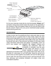
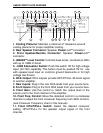
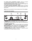
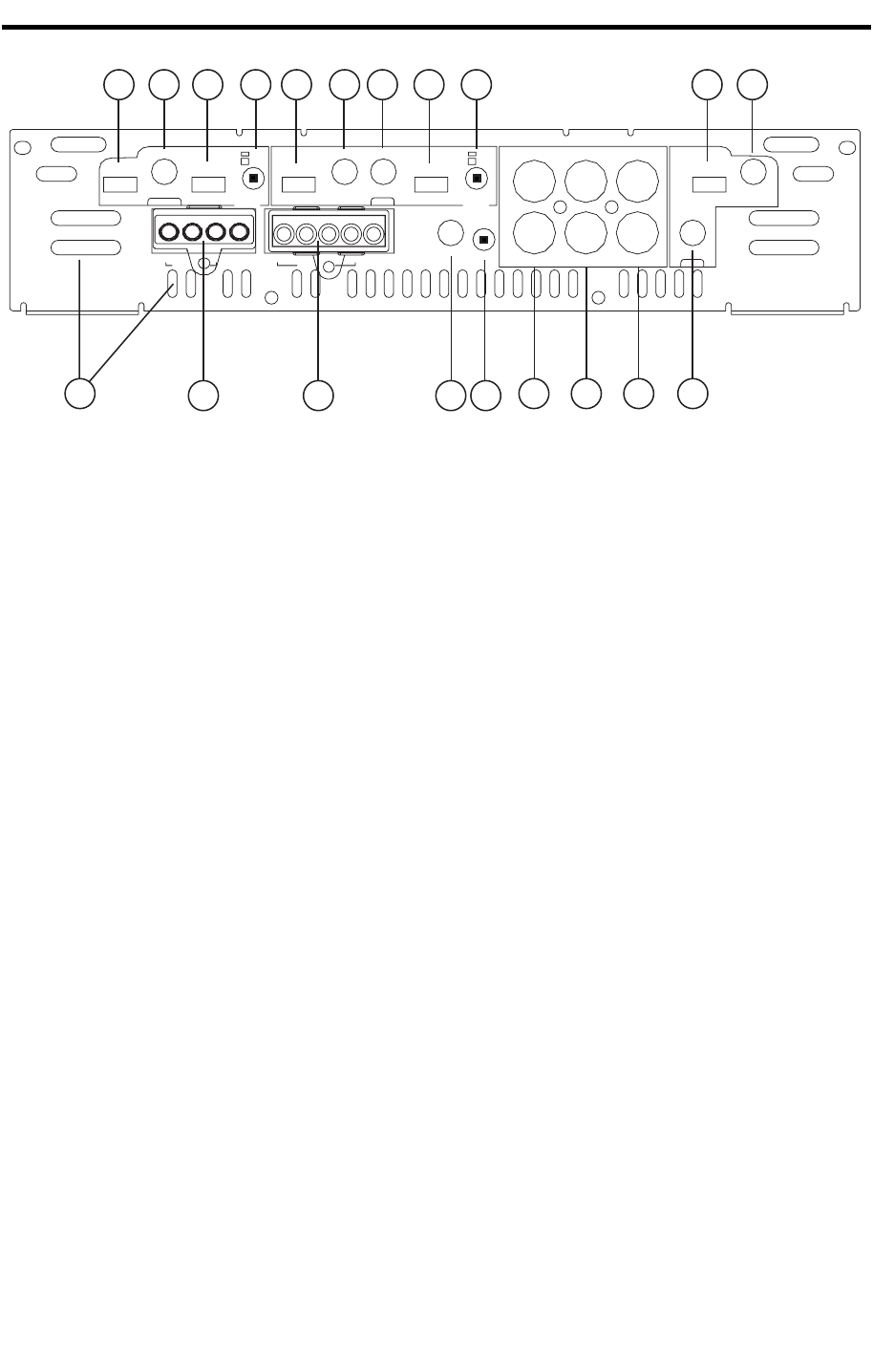
FRONT PLATE DIAGRAM
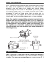
1. Cooling Plenums: Maintain a minimum 2” clearance around
cooling plenums for proper amplifier cooling.
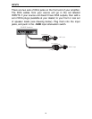
2. Rear Speaker Connector: Speaker
PowerLock
TM
connector.
3. Front Speaker/Remote Connector: Speaker
PowerLock
TM
connector.
4.
QBASS
TM
Level Control: Controls bass boost, centered at 40Hz
with up to 18dB of boost.
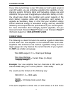
5. -12dB Attenuation Switch: Push this switch ‘IN’ for high voltage
input (4V-12V) capability. This button must be pushed ‘IN’ for use
with speaker level input on common ground head-units or for high
voltage line drivers.
6. RCA Output: RCA outputs provide HP/LP/FULL 30-4kHz signal
to another amplifier.
7. Rear Inputs: Plug in the rear RCA leads from your source here.
8. Front Inputs: Plug in the front RCA leads from your source here.
9. Front Gain: Use this control to match the output level of the
source unit to the front channel of the amplifier.
10. Front Freq. Control: Move this detented control in a clockwise
direction to adjust the front crossover frequency from 30Hz to4 kHz.
(see Crossover Frequency chart in this manual).
11. Front HP/LP/FULL Switch: Select the desired crossover
setting. HP/LP/FULL for the speaker output signal of the front
channel.
FREQ
LP
FULL
HP
30 4K
OUTPUTS
LP
FULL
HP
SOURCE
SUM
REAR
LP
FULL
HP
FREQ
30 4K
LP
FULL
HP
GAIN
MIN MAX
REAR
SOURCE
INT
EXT
QBASS
ATT
OUTPUT REAR
R
FRONT
LP
FULL HP
GAIN
ININOUT
L
RR- RR+ RL+ RL-
BRIDGED
FR- FR+ REM FL+ FL-
BRIDGED
0 +12dB
-12dB
MIN MAX
FRONT
FREQ
30 4K
1 6 7 8 9
54
1011
32
121314151617181920
15