


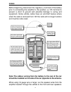
Observe the same precautions for routing these wires that you
followed for running the power and remote turn on wires. Cut off
excess and, using wire strippers, strip 1/4-inch of insulation. Locate
the front speaker/remote turn-on
PowerLock
TM
connector. Using a hex
wrench loosen the screws on the upperside of the connector. Insert
the front speaker leads into the end and secure with the hex wrench.
Check to be sure you've maintained proper polarity before securing
each wire.
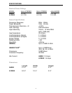
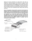
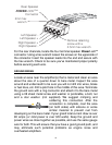
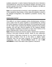
Note: The amplifier comes with the connector inserted into the
amplifier with the wire clamping screws in the up position as
shown below. Use a 2mm hex head wrench to secure the wires
to the connector. If the connector needs to be unplugged from
the amplifier, use a 2.5mm hex head wrench to remove the
retaining screw from the connector (set aside and save the
retaining screw).The two negative outputs are common to each
other as are the two positive outputs. A speaker may be
connected to either terminal.
Front Speaker
POWERLOCK
TM
Connector
Left Speaker -
Left Speaker +
Remote turn on
Right Speaker +
Ri
g
ht Speaker -
2mm hex
wrench
Remove retaining
screw with a
2.5mm hex wrench
9